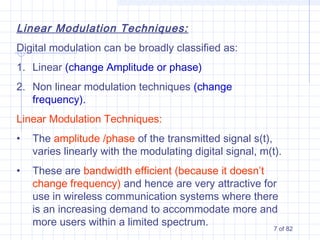
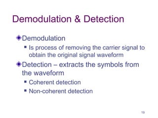
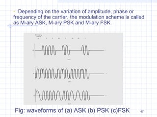
Digital modulation techniques change aspects of a carrier signal to transmit information. This document discusses various digital modulation methods including:
- Amplitude modulation (AM) which varies the amplitude (A) of the carrier.
- Frequency modulation (FM) which varies the frequency (ω) of the carrier.
- Phase modulation (PM) which varies the phase (φ) of the carrier.
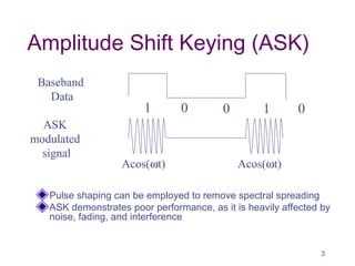
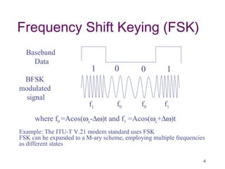
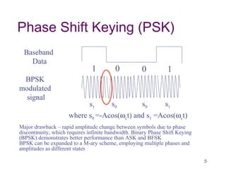
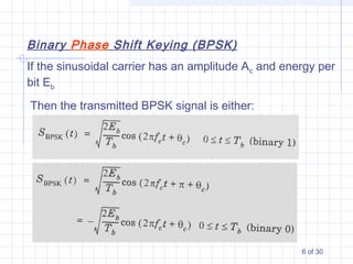
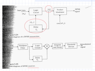
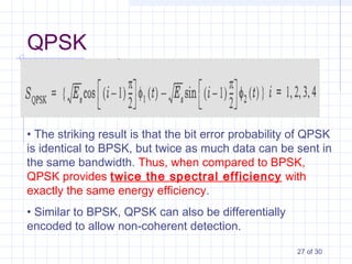
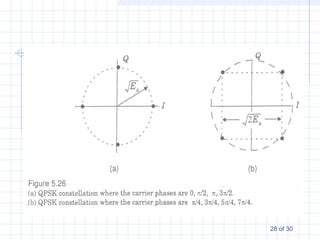
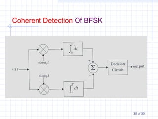
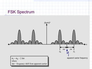
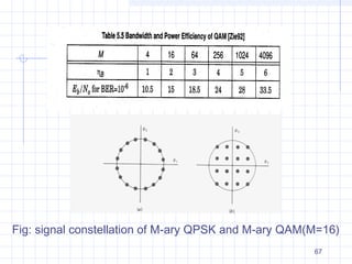
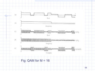
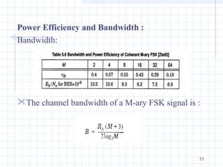
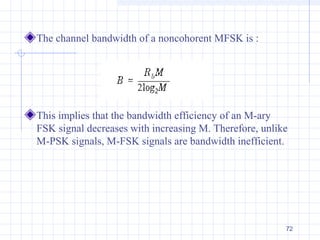
It then discusses specific modulation techniques including amplitude shift keying (ASK), frequency shift keying (FSK), phase shift keying (PSK) and their variants like quadrature phase shift keying (QPSK). The document provides illustrations of the modulated signals and discusses their bandwidth efficiency and performance in noise.

![Change which part of the
Carrier?
Carrier: A sin[ωt +ϕ]
A = const
ω = const
ϕ = const
Amplitude modulation
(AM)
A = A(t) – carries information
ω = const
ϕ = const
Frequency modulation
(FM)
A = const
ω = ω(t)– carries information
ϕ = const
Phase modulation (PM)
A = const
ω = const
ϕ = ϕ(t) – carries information
2](https://image.slidesharecdn.com/modulation-150408014423-conversion-gate01/85/Modulation-2-320.jpg)