This document discusses various techniques for encoding signals for wireless transmission, including:
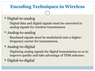
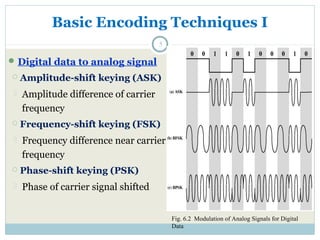
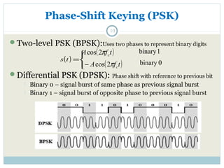
- Digital data must be converted to analog signals using techniques like amplitude-shift keying, frequency-shift keying, and phase-shift keying. Analog signals can also be modulated to higher frequencies for transmission.
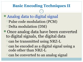
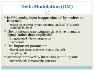
- Analog signals can be converted to digital for transmission using pulse code modulation (PCM) or delta modulation (DM). PCM assigns a binary code to analog samples while DM approximates the analog signal as a staircase function.
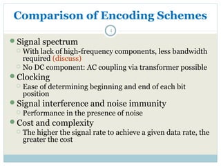
- Key factors in signal encoding are the signal-to-noise ratio, data rate, bandwidth, clocking, interference immunity, and cost/complexity of the scheme. Higher data rates