Downloaded 576 times


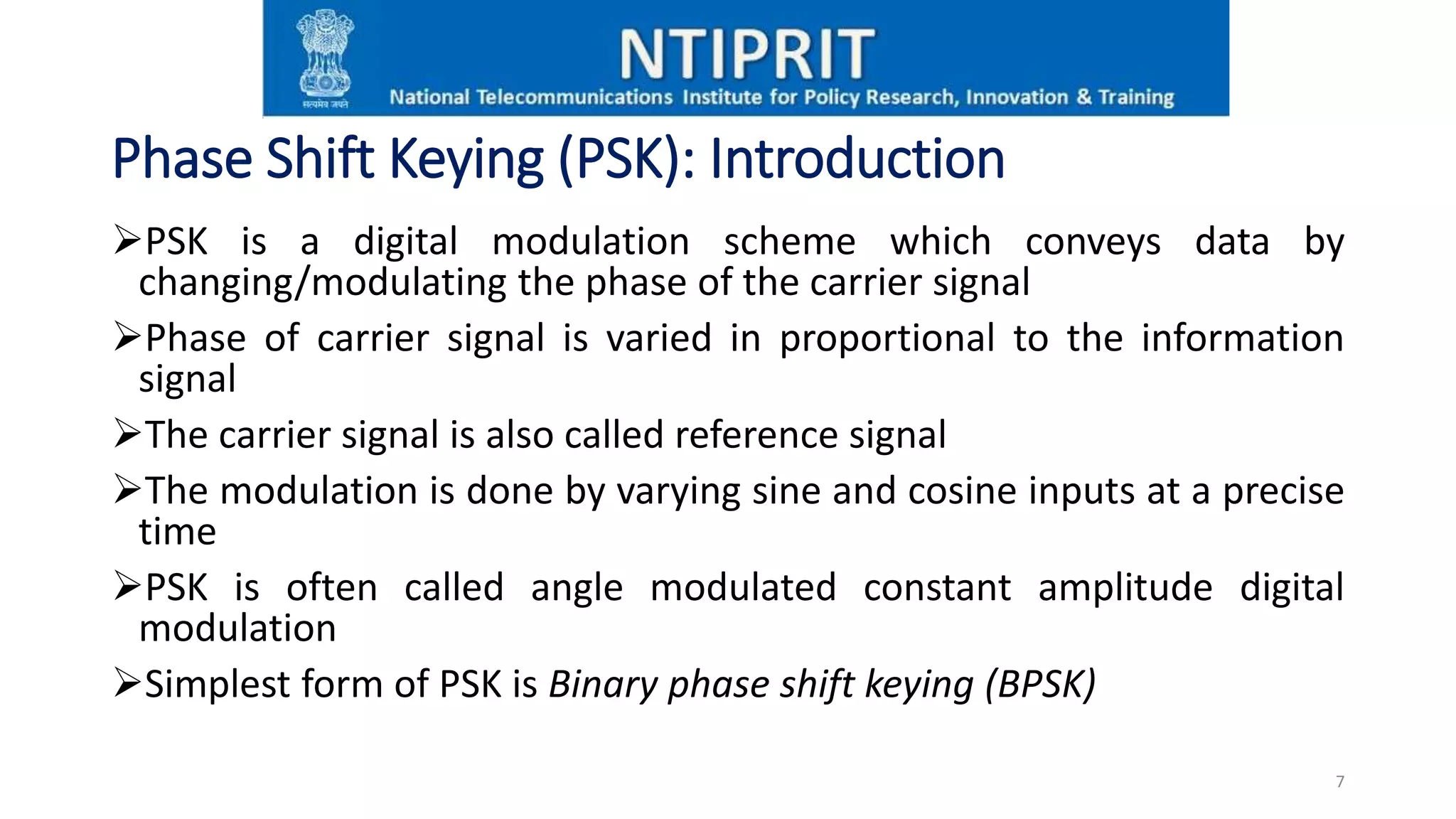


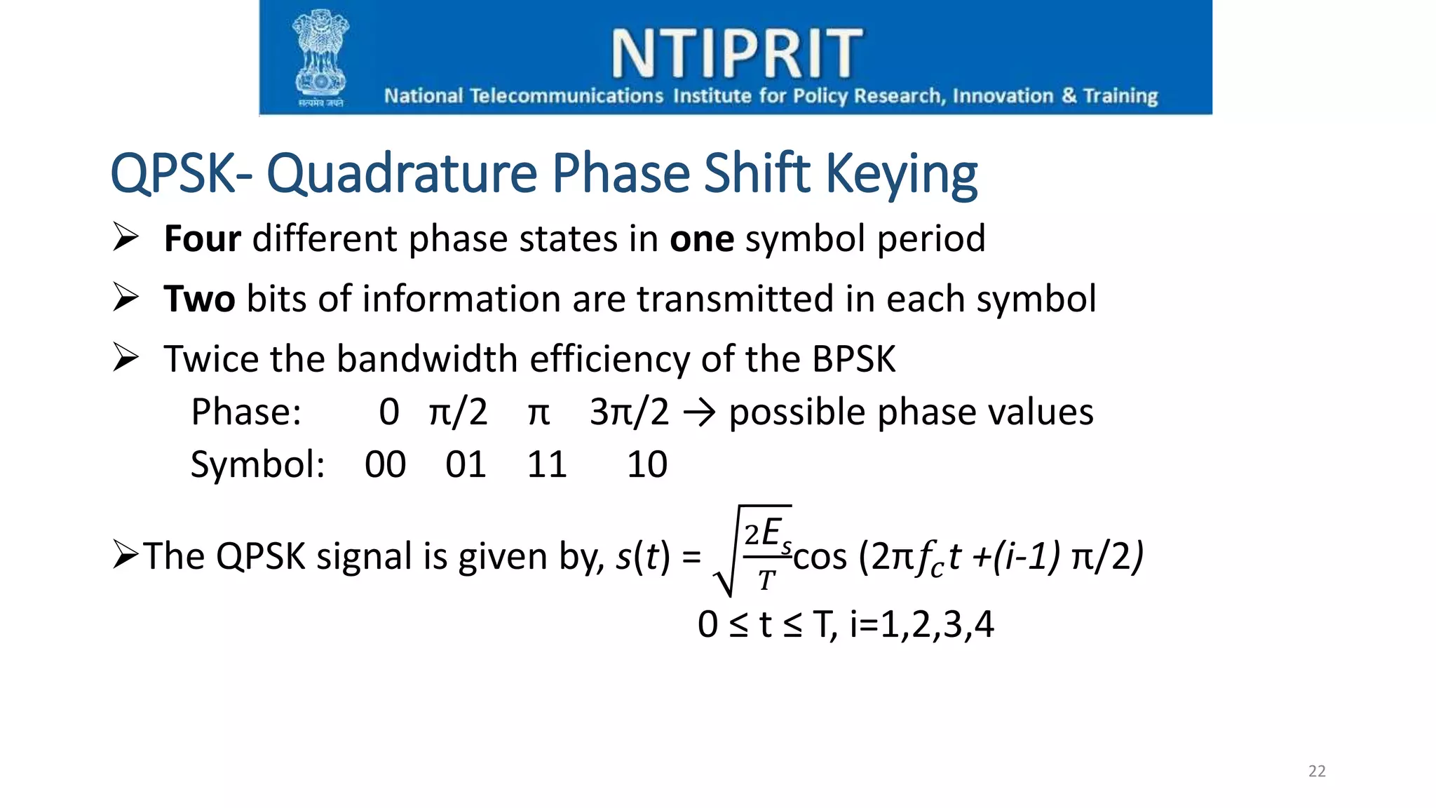

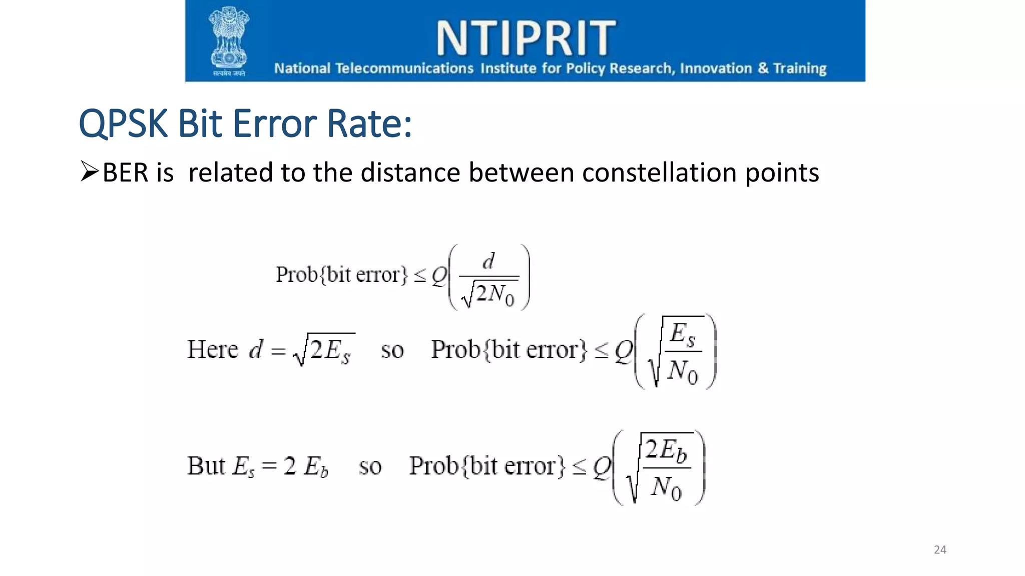

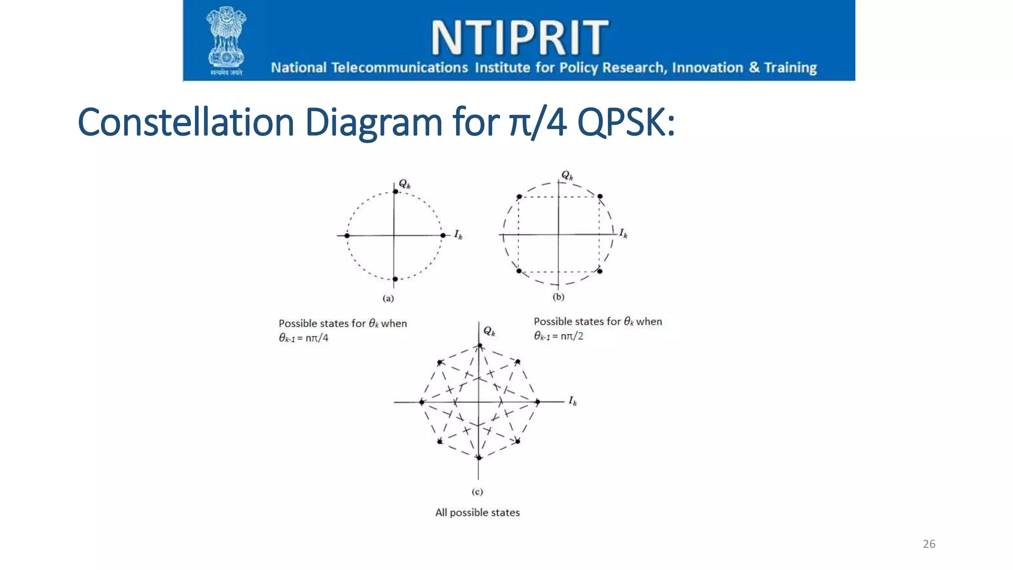


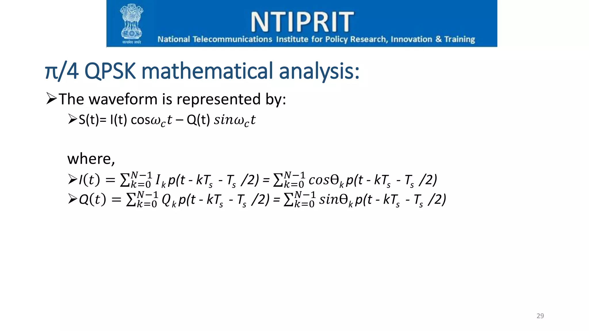


The presentation covers digital communication concepts and phase shift keying (PSK), including binary PSK (BPSK) and π/4-quadrature PSK (QPSK). It explains their modulation techniques, advantages, disadvantages, and applications, highlighting the significance of bandwidth and information capacity. The document also details the design of BPSK transmitters and receivers, along with alternative PSK schemes like 8-PSK and QAM.