Downloaded 572 times


![I&Q Signals
The resulting waveform is divided into In-Phase and
Quadrature components
In-phase: (Left)
Quadrature: (Right)
The two signal components are then up-converted to the
carrier frequency
I(t) = cos[c(t)] Q(t) = sin[c(t)]
16](https://image.slidesharecdn.com/gmsk-150621065203-lva1-app6891/85/Gmsk-16-320.jpg)
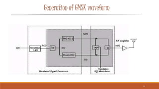
![GMSK Waveform
upconverting the I(t) produces
= cos[c(t)] cos((2Πfct)
Upconverting the Q(t) produces
= -sin[c(t)] sin(2Πfct)
m(t)= cos (2Πfct) I(t) + (-sin(2Πfct) Q(t))
17](https://image.slidesharecdn.com/gmsk-150621065203-lva1-app6891/85/Gmsk-17-320.jpg)


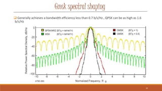


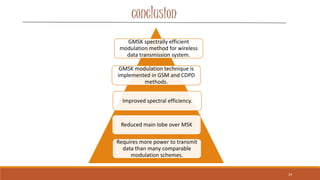


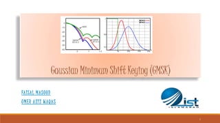
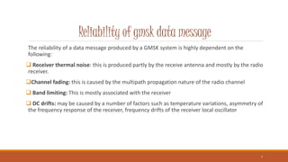
Gaussian Minimum Shift Keying (GMSK) is a form of continuous-phase frequency shift keying that uses a Gaussian filter to generate a constant envelope signal. It provides better spectral efficiency than MSK through bandwidth reduction while maintaining low intersymbol interference. GMSK is used widely in wireless technologies like GSM and CDPD due to its power efficiency and good bit error rate performance compared to other modulation schemes. While more spectrally efficient than MSK, GMSK also has slightly higher error rates and requires more complex receivers.


