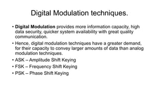
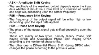
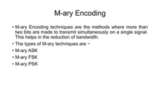
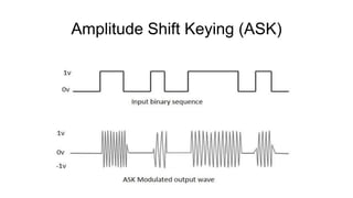
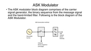
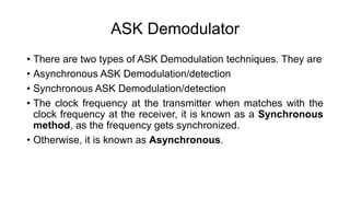
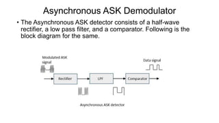
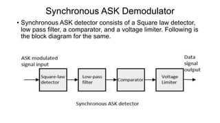
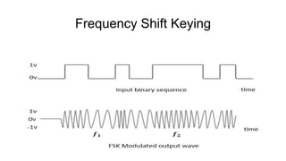
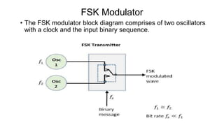
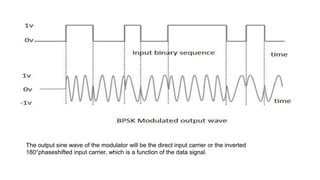
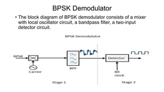
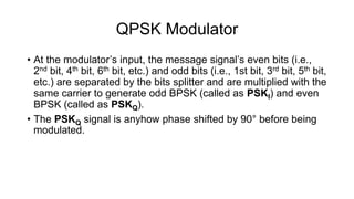
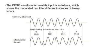
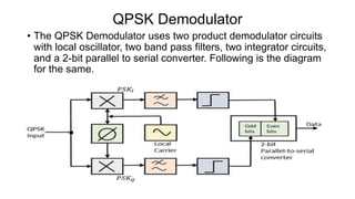
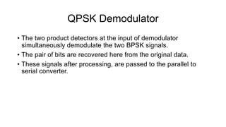
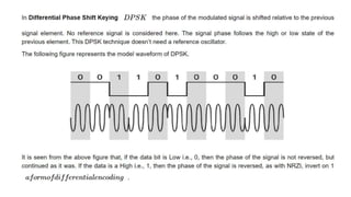
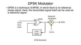
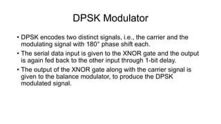
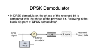
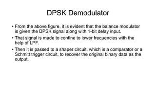
This document discusses various digital modulation techniques used in digital communications. It describes amplitude shift keying (ASK), frequency shift keying (FSK), phase shift keying (PSK) including binary PSK (BPSK) and quadrature PSK (QPSK). It provides block diagrams and explanations of modulators and demodulators for ASK, FSK, BPSK and QPSK. It also discusses M-ary encoding techniques that can transmit more than two bits simultaneously to reduce bandwidth.
Salient Features:
The magnitude response is nearly constant(equal to 1) at lower frequencies
There are no ripples in passband and stop band
The maximum gain occurs at Ω=0 and it is H(Ω)=1
The magnitude response is monotonically decreasing
As the order of the filter ‘N’ increases, the response of the filter is more close to the ideal response
This presentation contain each and every single information on the topic.
If you like it do follow and like my presentation.
It would be worth my efforts.
Frequency-Shift Keying, also known as FSK is a type of digital frequency modulation. It is also often called as binary frequency shift keying or BFSK
Similar to analog FM, it is a constant-amplitude angle modulation.
This presentation will discuss the concepts behind FSK
Digital data is represented as variations in the amplitude of a carrier wave in amplitude-shift keying (ASK), a type of modulation.
In an ASK system, a symbol, representing one or more bits, is sent by transmitting a fixed-amplitude carrier wave at a fixed frequency for a specific time duration.
A simple form of ASK modulation is considered that amplitude modulates a carrier based on a direct mapping of the source data bits to the waveform symbol. The most rudimentary form of ASK is given the special name On–Off Keying (OOK) modulation.
It is a digital representation of an analog signal that takes samples of the amplitude of the analog signal at regular intervals. The sampled analog data is changed to, and then represented by, binary data.
Base band transmission
*Wave form representation of binary digits
*PCM, DPCM, DM, ADM systems
*Detection of signals in Gaussian noise
*Matched filter - Application of matched filter
*Error probability performance of binary signaling
*Multilevel base band transmission
*Inter symbol interference
*Eye pattern
*Companding
*A law and μ law
*Correlation receiver
This presentation covers:
Some basic definitions & concepts of digital communication
What is Phase Shift Keying(PSK) ?
Binary Phase Shift Keying – BPSK
BPSK transmitter & receiver
Advantages & Disadvantages of BPSK
Pi/4 – QPSK
Pi/4 – QPSK transmitter & receiver
Advantages of Pi/4- QPSK
The Quadrature Phase Shift Keying QPSK is a variation of BPSK, and it is also a Double Side Band Suppressed Carrier DSBSC modulation scheme, which sends two bits of digital information at a time, called as bigits.
Instead of the conversion of digital bits into a series of digital stream, it converts them into bit pairs. This decreases the data bit rate to half, which allows space for the other users.
QPSK (Quadrature Phase Shift Keying) is type of phase shift keying. Unlike BPSK which is a DSBCS modulation scheme with digital information for the message, QPSK is also a DSBCS modulation scheme but it sends two bits of digital information a time (without the use of another carrier frequency).
The amount of radio frequency spectrum required to transmit QPSK reliably is half that required for BPSK signals, which in turn makes room for more users on the channel.
Phase-shift keying (PSK) is a digital modulation scheme that conveys data by changing (modulating) the phase of a reference signal (the carrier wave). The modulation is impressed by varying the sine and cosine inputs at a precise time. It is widely used for wireless LANs, RFID and Bluetooth communication
Frequency-shift keying (FSK) is a frequency modulation scheme in which digital information is transmitted through discrete frequency changes of a carrier signal.[1] The technology is used for communication systems such as amateur radio, caller ID and emergency broadcasts
This slide describe the techniques of digital modulation and Bandwidth Efficiency:
The first null bandwidth of M-ary PSK signals decrease as M increases while Rb is held constant.
Therefore, as the value of M increases, the bandwidth efficiency also increases.
Water scarcity is the lack of fresh water resources to meet the standard water demand. There are two type of water scarcity. One is physical. The other is economic water scarcity.
Student information management system project report ii.pdfKamal Acharya
Our project explains about the student management. This project mainly explains the various actions related to student details. This project shows some ease in adding, editing and deleting the student details. It also provides a less time consuming process for viewing, adding, editing and deleting the marks of the students.
Welcome to WIPAC Monthly the magazine brought to you by the LinkedIn Group Water Industry Process Automation & Control.
In this month's edition, along with this month's industry news to celebrate the 13 years since the group was created we have articles including
A case study of the used of Advanced Process Control at the Wastewater Treatment works at Lleida in Spain
A look back on an article on smart wastewater networks in order to see how the industry has measured up in the interim around the adoption of Digital Transformation in the Water Industry.
Explore the innovative world of trenchless pipe repair with our comprehensive guide, "The Benefits and Techniques of Trenchless Pipe Repair." This document delves into the modern methods of repairing underground pipes without the need for extensive excavation, highlighting the numerous advantages and the latest techniques used in the industry.
Learn about the cost savings, reduced environmental impact, and minimal disruption associated with trenchless technology. Discover detailed explanations of popular techniques such as pipe bursting, cured-in-place pipe (CIPP) lining, and directional drilling. Understand how these methods can be applied to various types of infrastructure, from residential plumbing to large-scale municipal systems.
Ideal for homeowners, contractors, engineers, and anyone interested in modern plumbing solutions, this guide provides valuable insights into why trenchless pipe repair is becoming the preferred choice for pipe rehabilitation. Stay informed about the latest advancements and best practices in the field.
CFD Simulation of By-pass Flow in a HRSG module by R&R Consult.pptxR&R Consult
CFD analysis is incredibly effective at solving mysteries and improving the performance of complex systems!
Here's a great example: At a large natural gas-fired power plant, where they use waste heat to generate steam and energy, they were puzzled that their boiler wasn't producing as much steam as expected.
R&R and Tetra Engineering Group Inc. were asked to solve the issue with reduced steam production.
An inspection had shown that a significant amount of hot flue gas was bypassing the boiler tubes, where the heat was supposed to be transferred.
R&R Consult conducted a CFD analysis, which revealed that 6.3% of the flue gas was bypassing the boiler tubes without transferring heat. The analysis also showed that the flue gas was instead being directed along the sides of the boiler and between the modules that were supposed to capture the heat. This was the cause of the reduced performance.
Based on our results, Tetra Engineering installed covering plates to reduce the bypass flow. This improved the boiler's performance and increased electricity production.
It is always satisfying when we can help solve complex challenges like this. Do your systems also need a check-up or optimization? Give us a call!
Work done in cooperation with James Malloy and David Moelling from Tetra Engineering.
More examples of our work https://www.r-r-consult.dk/en/cases-en/
2. Digital Modulation techniques.
• Digital Modulation provides more information capacity, high
data security, quicker system availability with great quality
communication.
• Hence, digital modulation techniques have a greater demand,
for their capacity to convey larger amounts of data than analog
modulation techniques.
• ASK – Amplitude Shift Keying
• FSK – Frequency Shift Keying
• PSK – Phase Shift Keying
3. • ASK – Amplitude Shift Keying
• The amplitude of the resultant output depends upon the input
data whether it should be a zero level or a variation of positive
and negative, depending upon the carrier frequency.
• FSK – Frequency Shift Keying
• The frequency of the output signal will be either high or low,
depending upon the input data applied.
• PSK – Phase Shift Keying
• The phase of the output signal gets shifted depending upon the
input.
• These are mainly of two types, namely Binary Phase Shift
Keying BPSK and Quadrature Phase Shift Keying QPSK
according to the number of phase shifts.
• The other one is Differential Phase Shift Keying DPSK which
changes the phase according to the previous value.
4. M-ary Encoding
• M-ary Encoding techniques are the methods where more than
two bits are made to transmit simultaneously on a single signal.
This helps in the reduction of bandwidth.
• The types of M-ary techniques are −
• M-ary ASK
• M-ary FSK
• M-ary PSK
5. Amplitude Shift Keying (ASK)
• ASK is a type of Amplitude Modulation which represents the
binary data in the form of variations in the amplitude of a signal.
• Any modulated signal has a high frequency carrier.
• The binary signal when ASK modulated, gives a zero value
for Low input while it gives the carrier output for High input.
• The following figure represents ASK modulated waveform along
with its input.
7. ASK Modulator
• The ASK modulator block diagram comprises of the carrier
signal generator, the binary sequence from the message signal
and the band-limited filter. Following is the block diagram of the
ASK Modulator.
8. ASK Modulator
• The carrier generator, sends a continuous high-frequency
carrier. The binary sequence from the message signal makes
the unipolar input to be either High or Low. The high signal
closes the switch, allowing a carrier wave.
• Hence, the output will be the carrier signal at high input. When
there is low input, the switch opens, allowing no voltage to
appear. Hence, the output will be low.
• The band-limiting filter, shapes the pulse depending upon the
amplitude and phase characteristics of the band-limiting filter or
the pulse-shaping filter.
9. ASK Demodulator
• There are two types of ASK Demodulation techniques. They are
• Asynchronous ASK Demodulation/detection
• Synchronous ASK Demodulation/detection
• The clock frequency at the transmitter when matches with the
clock frequency at the receiver, it is known as a Synchronous
method, as the frequency gets synchronized.
• Otherwise, it is known as Asynchronous.
10. Asynchronous ASK Demodulator
• The Asynchronous ASK detector consists of a half-wave
rectifier, a low pass filter, and a comparator. Following is the
block diagram for the same.
11. Asynchronous ASK Demodulator
• The modulated ASK signal is given to the half-wave rectifier,
which delivers a positive half output.
• The low pass filter suppresses the higher frequencies and gives
an envelope detected output from which the comparator
delivers a digital output.
12. Synchronous ASK Demodulator
• Synchronous ASK detector consists of a Square law detector,
low pass filter, a comparator, and a voltage limiter. Following is
the block diagram for the same.
13. Synchronous ASK Demodulator
• The ASK modulated input signal is given to the Square law
detector.
• A square law detector is one whose output voltage is
proportional to the square of the amplitude modulated input
voltage.
• The low pass filter minimizes the higher frequencies. The
comparator and the voltage limiter help to get a clean digital
output.
14. Frequency Shift Keying
• FSK is the digital modulation technique in which the frequency
of the carrier signal varies according to the digital signal
changes. FSK is a scheme of frequency modulation.
• The output of a FSK modulated wave is high in frequency for a
binary High input and is low in frequency for a binary Low input.
• The binary 1s and 0s are called Mark and Space frequencies.
16. FSK Modulator
• The FSK modulator block diagram comprises of two oscillators
with a clock and the input binary sequence.
17. FSK Modulator
• The two oscillators, producing a higher and a lower frequency
signals, are connected to a switch along with an internal clock.
• To avoid the abrupt phase discontinuities of the output
waveform during the transmission of the message, a clock is
applied to both the oscillators, internally.
• The binary input sequence is applied to the transmitter so as to
choose the frequencies according to the binary input.
18. FSK Demodulator
• There are different methods for demodulating a FSK wave. The
main methods of FSK detection are asynchronous
detector and synchronous detector.
• The synchronous detector is a coherent one, while
asynchronous detector is a non-coherent one.
19. Asynchronous FSK Detector
• The block diagram of Asynchronous FSK detector consists of
two band pass filters, two envelope detectors, and a decision
circuit.
20. Asynchronous FSK Detector
• The FSK signal is passed through the two Band Pass Filters.
BPFs tuned to Space and Mark frequencies.
• The output from these two BPFs look like ASK signal, which is
given to the envelope detector.
• The signal in each envelope detector is modulated
asynchronously.
• The decision circuit chooses which output is more likely and
selects it from any one of the envelope detectors. It also re-
shapes the waveform.
21. Synchronous FSK Detector
• The block diagram of Synchronous FSK detector consists of
two mixers with local oscillator circuits, two band pass filters
and a decision circuit.
22. Synchronous FSK Detector
• The FSK signal input is given to the two mixers with local
oscillator circuits. These two are connected to two band pass
filters.
• These combinations act as demodulators and the decision
circuit chooses which output is more likely and selects it from
any one of the detectors. The two signals have a minimum
frequency separation.
• For both of the demodulators, the bandwidth of each of them
depends on their bit rate. This synchronous demodulator is a bit
complex than asynchronous type demodulators.
23. Phase Shift Keying
• PSK is the digital modulation technique in which the phase of
the carrier signal is changed by varying the sine and cosine
inputs at a particular time.
• PSK technique is widely used for wireless LANs, bio-metric,
contactless operations, along with RFID and Bluetooth
communications.
• PSK is of two types, depending upon the phases the signal gets
shifted. They are −
• Binary Phase Shift Keying - BPSK
• Quadrature Phase Shift Keying - QPSK
24. Binary Phase Shift Keying - BPSK
• This is also called as 2-phase PSK or Phase Reversal Keying.
In this technique, the sine wave carrier takes two phase
reversals such as 0° and 180°.
• BPSK is basically a Double Side Band Suppressed Carrier
DSBSC modulation scheme, for message being the digital
information.
25. Quadrature Phase Shift Keying - QPSK
• This is the phase shift keying technique, in which the sine wave
carrier takes four phase reversals such as 0°, 90°, 180°, and
270°.
• If this kind of techniques are further extended, PSK can be done
by eight or sixteen values also, depending upon the
requirement
26. BPSK Modulator
• The block diagram of Binary Phase Shift Keying consists of the
balance modulator which has the carrier sine wave as one input
and the binary sequence as the other input. Following is the
diagrammatic representation.
27. BPSK Modulator
• The modulation of BPSK is done using a balance modulator,
which multiplies the two signals applied at the input.
• For a zero binary input, the phase will be 0° and for a high
input, the phase reversal is of 180°.
• Following is the diagrammatic representation of BPSK
Modulated output wave along with its given input.
28. The output sine wave of the modulator will be the direct input carrier or the inverted
180°phaseshifted input carrier, which is a function of the data signal.
29. BPSK Demodulator
• The block diagram of BPSK demodulator consists of a mixer
with local oscillator circuit, a bandpass filter, a two-input
detector circuit.
30. BPSK Demodulator
• By recovering the band-limited message signal, with the help of
the mixer circuit and the band pass filter, the first stage of
demodulation gets completed.
• The base band signal which is band limited is obtained and this
signal is used to regenerate the binary message bit stream.
• In the next stage of demodulation, the bit clock rate is needed at
the detector circuit to produce the original binary message
signal.
• If the bit rate is a sub-multiple of the carrier frequency, then the
bit clock regeneration is simplified.
31. Quadrature Phase Shift Keying
• QPSK is a variation of BPSK, and it is also a Double Side Band
Suppressed Carrier DSBSC modulation scheme, which sends
two bits of digital information at a time, called as bigits.
• Instead of the conversion of digital bits into a series of digital
stream, it converts them into bit pairs.
• This decreases the data bit rate to half, which allows space for
the other users.
32. QPSK Modulator
• The QPSK Modulator uses a bit-splitter, two multipliers with
local oscillator, a 2-bit serial to parallel converter, and a summer
circuit.
33. QPSK Modulator
• At the modulator’s input, the message signal’s even bits (i.e.,
2nd bit, 4th bit, 6th bit, etc.) and odd bits (i.e., 1st bit, 3rd bit, 5th bit,
etc.) are separated by the bits splitter and are multiplied with the
same carrier to generate odd BPSK (called as PSKI) and even
BPSK (called as PSKQ).
• The PSKQ signal is anyhow phase shifted by 90° before being
modulated.
34. • The QPSK waveform for two-bits input is as follows, which
shows the modulated result for different instances of binary
inputs.
35. QPSK Demodulator
• The QPSK Demodulator uses two product demodulator circuits
with local oscillator, two band pass filters, two integrator circuits,
and a 2-bit parallel to serial converter. Following is the diagram
for the same.
36. QPSK Demodulator
• The two product detectors at the input of demodulator
simultaneously demodulate the two BPSK signals.
• The pair of bits are recovered here from the original data.
• These signals after processing, are passed to the parallel to
serial converter.
37.
38. DPSK Modulator
• DPSK is a technique of BPSK, in which there is no reference
phase signal. Here, the transmitted signal itself can be used as
a reference signal.
39. DPSK Modulator
• DPSK encodes two distinct signals, i.e., the carrier and the
modulating signal with 180° phase shift each.
• The serial data input is given to the XNOR gate and the output
is again fed back to the other input through 1-bit delay.
• The output of the XNOR gate along with the carrier signal is
given to the balance modulator, to produce the DPSK
modulated signal.
40. DPSK Demodulator
• In DPSK demodulator, the phase of the reversed bit is
compared with the phase of the previous bit. Following is the
block diagram of DPSK demodulator.
41. DPSK Demodulator
• From the above figure, it is evident that the balance modulator
is given the DPSK signal along with 1-bit delay input.
• That signal is made to confine to lower frequencies with the
help of LPF.
• Then it is passed to a shaper circuit, which is a comparator or a
Schmitt trigger circuit, to recover the original binary data as the
output.