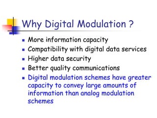
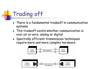
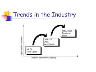
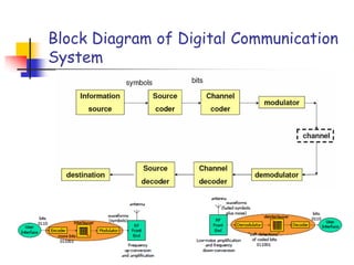
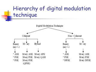
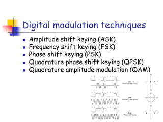
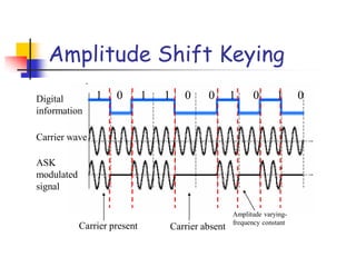
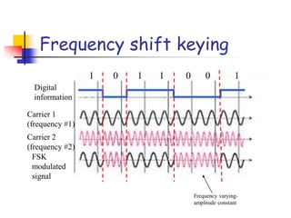
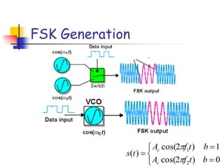
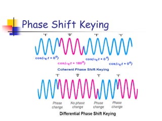
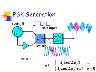
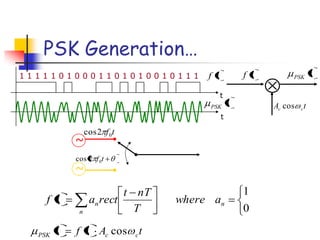
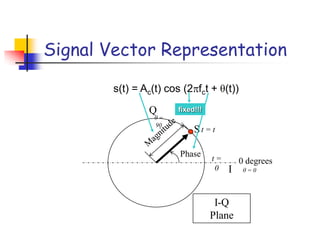
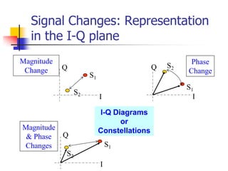
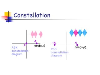
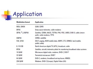
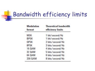
Digital Modulation Basics
N N Maurya
Why Digital Modulation ?
 More information capacity
 Compatibility with digital data services
 Higher data security
 Better quality communications
 Digital modulation schemes have greater
capacity to convey large amounts of
information than analog modulation
schemes
Constraints ?
 Available bandwidth
 Permissible power
 Inherent noise level of the system
Trading off
 There is a fundamental tradeoff in communication
systems
 This tradeoff exists whether communication is
over air or wire, analog or digital
 Spectrally efficient transmission techniques
require more and more complex hardware
Trends in the Industry
Block Diagram of Digital Communication
System
Classification of Communication
System
 Most communication systems can be classified into
one of three different categories:
– Bandwidth efficient
Ability of system to accommodate data
within a prescribed bandwidth
– Power efficient
Reliable sending of data with minimal power
requirements
– Cost efficient
System needs to be affordable in the context
of its use
Types of Digital Modulation System
 COHERENT
 NON- COHERENT
 Coherent (synchronous) detection: process receives
signal with a local carrier of same frequency and
phase
 Non coherent (envelope) detection: requires no
reference wave
TYPES OF DIGITAL MODULATION
SYSTEM……
 Coherent detection
 Receiver uses the carrier phase to detect signal
 Cross correlate with replica signals at receiver
 Match within threshold to make decision
 Non coherent detection
 Does not exploit phase reference information
 Less complex receiver, but worse performance
Hierarchy of digital modulation
technique
Digital modulation techniques
 Amplitude shift keying (ASK)
 Frequency shift keying (FSK)
 Phase shift keying (PSK)
 Quadrature phase shift keying (QPSK)
 Quadrature amplitude modulation (QAM)
Metrics for Digital Modulation
 Power Efficiency
 Power efficiency is a measure of how much
signal power should be increased to achieve a
particular BER for a given modulation scheme
 Ability of a modulation technique to preserve
the fidelity of the digital message at low power
levels
 Designer can increase noise immunity by
increasing signal power
 Signal energy per bit / noise power spectral
density: Eb / N0
Metrics for Digital Modulation…
 Bandwidth Efficiency
 Ability to accommodate data within a limited
bandwidth
 Tradeoff between data rate and pulse width
 Data rate per hertz: R/B bps per Hz
 Shannon Limit: Channel capacity /
bandwidth
 C = B log2(1 + S/N) OR
 C/B = log2(1 + S/N)
Considerations in Choice of
Modulation Scheme
 High spectral efficiency
 High power efficiency
 Robust to multipath effects
 Low cost and ease of implementation
 Low carrier-to-cochannel interference
ratio
 Low out-of-band radiation
 Constant or near constant envelope
 Constant: only phase is modulated
 Non-constant: phase and amplitude modulated
Amplitude Shift Keying
Digital
information
1 0 1 1 0 0 1 0 1 0
Carrier wave
ASK
modulated
signal
Carrier present Carrier absent
Amplitude varying-
frequency constant
ASK Generation
Lower Side band Upper Side band
Band width=2 X Modulating freq.
00
1)2cos(
)(
tfA
ts cc
1 1 1 1 1 0 1 0 0 0 1 1 0 1 0 1 0 0 1 0 1 1 1
t
t
tf
tASK
tf tASK
tA cc sin
n
nn awhere
T
nTt
rectatf
0
1
tAtft ccASK sin
0
sin tA
t cc
ASK
(logic 1)
(logic 0)
ASK Generation…
ASK Detection
Necessity to shape the pulse
A pulse contains infinite number of harmonics and hence bandwidth
Frequency shift keying
Digital
information
1 0 1 1 0 0 1
Carrier 1
(frequency #1)
FSK
modulated
signal
Carrier 2
(frequency #2)
Frequency varying-
amplitude constant
FSK Generation
0)2cos(
1)2cos(
)(
2
1
btfA
btfA
ts
c
c
FSK Detection
Minimum Shift Keying
 When the frequency of the
separation becomes lowest it is known
as minimum shift keying (MSK)
Phase Shift Keying
PSK Generation
1800 shift
0)2cos(
1)2cos(
)(
btfA
btfA
ts
cc
cc
PSK Generation…
n
nn awhere
T
nTt
rectatf
0
1
tAtft ccPSK cos
tf tPSK
tA cc cos
1 1 1 1 1 0 1 0 0 0 1 1 0 1 0 1 0 0 1 0 1 1 1
t
t
tf
tPSK
~
~
tf02cos
tf02cos
Signal Vector Representation
Phase
S
0 degrees
I
Q
I-Q
Plane
s(t) = Ac(t) cos (2 fct + θ(t))
fixed!!!
t =
0
t = t
θ =
90
θ = 0
S1
S2
I
Q
Magnitude
Change
S1
S2
I
Q
Phase
Change
S1
S2
I
Q
Magnitude
& Phase
Changes
I-Q Diagrams
or
Constellations
Signal Changes: Representation
in the I-Q plane
Constellation
QPSK
 The only way to achieve high data rates with a
narrowband channel is to increase the number of
bits/symbol
 The most reliable way to do this is with a combination
of amplitude and phase modulation called quadrature
amplitude modulation (QAM)
 Quadrature Phase Shift Keying is effectively two
independent BPSK
 QPSK systems (I and Q), exhibits the same
performance but twice the bandwidth efficiency of
that of BPSK.
 Large envelope variations occur during phase
transitions, thus requiring linear amplification.
QPSK constellation
Basic QPSK constellation QPSK constellation Shifted by 450
QPSK……
Carrier phase is changed by 450 ,1350, 2250, 3150
00 10 11 10 01
QPSK Generation
QPSK Detection
Types of QPSK
 Conventional QPSK has transitions through zero
(i.e. 180 phase transition). Highly linear amplifier
required.
 In Offset QPSK, the transitions on the I and Q
channels are staggered.
 Phase transitions are therefore limited to
90degrees.
 In /4-QPSK the set of constellation points are
toggled each symbol, so transitions through zero
cannot occur. This scheme produces the lowest
envelope variations.
 All QPSK schemes require linear power amplifiers.
Offset QPSK
/4 QPSK
Multi-level (M-ary) Phase and
Amplitude Modulation
 Amplitude and phase shift keying can be combined
to transmit several bits per symbol
 These modulation schemes are often referred to
as linear, as they require linear amplification
 Amplitude modulation on both quadrature carriers
 2^n discrete levels, n = 2 same as QPSK
 16-QAM has the largest distance between points,
but requires very linear amplification. 16-PSK has
less stringent linearity requirements, but has less
spacing between constellation points, and is
therefore more affected by noise
 M-ary schemes are more bandwidth efficient, but
more susceptible to noise.
16-QAM
16-QAM Generation
16-QAM Detection
16QAM with different impairments
AWGN
Loss
of
Sync
Interference
Phase
Noise
Application
Bandwidth efficiency limits
Thank You!
Actual example
 Here is a 16-level constellation which is
reconstructed in the presence of noise
-2 -1.5 -1 -0.5 0 0.5 1 1.5 2
-2
-1.5
-1
-0.5
0
0.5
1
1.5
2
Eb/No=5 dB
Defining decision regions
 An easy detection method, is to compute “decision
regions” offline. Here are a few examples
decide s1
decide s2
s1s2
measurement
decide s1
decide s2
decide s3 decide s4
s1s2
s3 s4
decide s1
s1
On-off keying (OOK)
 Simplest/oldest form of modulation
 Morse code (1837) – developed for telegraphy
Eye diagrams

Digital modulation basics(nnm)

  • 1.
  • 2.
    Why Digital Modulation?  More information capacity  Compatibility with digital data services  Higher data security  Better quality communications  Digital modulation schemes have greater capacity to convey large amounts of information than analog modulation schemes
  • 3.
    Constraints ?  Availablebandwidth  Permissible power  Inherent noise level of the system
  • 4.
    Trading off  Thereis a fundamental tradeoff in communication systems  This tradeoff exists whether communication is over air or wire, analog or digital  Spectrally efficient transmission techniques require more and more complex hardware
  • 5.
    Trends in theIndustry
  • 6.
    Block Diagram ofDigital Communication System
  • 7.
    Classification of Communication System Most communication systems can be classified into one of three different categories: – Bandwidth efficient Ability of system to accommodate data within a prescribed bandwidth – Power efficient Reliable sending of data with minimal power requirements – Cost efficient System needs to be affordable in the context of its use
  • 8.
    Types of DigitalModulation System  COHERENT  NON- COHERENT  Coherent (synchronous) detection: process receives signal with a local carrier of same frequency and phase  Non coherent (envelope) detection: requires no reference wave
  • 9.
    TYPES OF DIGITALMODULATION SYSTEM……  Coherent detection  Receiver uses the carrier phase to detect signal  Cross correlate with replica signals at receiver  Match within threshold to make decision  Non coherent detection  Does not exploit phase reference information  Less complex receiver, but worse performance
  • 10.
    Hierarchy of digitalmodulation technique
  • 11.
    Digital modulation techniques Amplitude shift keying (ASK)  Frequency shift keying (FSK)  Phase shift keying (PSK)  Quadrature phase shift keying (QPSK)  Quadrature amplitude modulation (QAM)
  • 12.
    Metrics for DigitalModulation  Power Efficiency  Power efficiency is a measure of how much signal power should be increased to achieve a particular BER for a given modulation scheme  Ability of a modulation technique to preserve the fidelity of the digital message at low power levels  Designer can increase noise immunity by increasing signal power  Signal energy per bit / noise power spectral density: Eb / N0
  • 13.
    Metrics for DigitalModulation…  Bandwidth Efficiency  Ability to accommodate data within a limited bandwidth  Tradeoff between data rate and pulse width  Data rate per hertz: R/B bps per Hz  Shannon Limit: Channel capacity / bandwidth  C = B log2(1 + S/N) OR  C/B = log2(1 + S/N)
  • 14.
    Considerations in Choiceof Modulation Scheme  High spectral efficiency  High power efficiency  Robust to multipath effects  Low cost and ease of implementation  Low carrier-to-cochannel interference ratio  Low out-of-band radiation  Constant or near constant envelope  Constant: only phase is modulated  Non-constant: phase and amplitude modulated
  • 15.
    Amplitude Shift Keying Digital information 10 1 1 0 0 1 0 1 0 Carrier wave ASK modulated signal Carrier present Carrier absent Amplitude varying- frequency constant
  • 16.
    ASK Generation Lower Sideband Upper Side band Band width=2 X Modulating freq. 00 1)2cos( )( tfA ts cc
  • 17.
    1 1 11 1 0 1 0 0 0 1 1 0 1 0 1 0 0 1 0 1 1 1 t t tf tASK tf tASK tA cc sin n nn awhere T nTt rectatf 0 1 tAtft ccASK sin 0 sin tA t cc ASK (logic 1) (logic 0) ASK Generation…
  • 18.
  • 19.
    Necessity to shapethe pulse A pulse contains infinite number of harmonics and hence bandwidth
  • 20.
    Frequency shift keying Digital information 10 1 1 0 0 1 Carrier 1 (frequency #1) FSK modulated signal Carrier 2 (frequency #2) Frequency varying- amplitude constant
  • 21.
  • 22.
  • 23.
    Minimum Shift Keying When the frequency of the separation becomes lowest it is known as minimum shift keying (MSK)
  • 24.
  • 25.
  • 26.
    PSK Generation… n nn awhere T nTt rectatf 0 1 tAtftccPSK cos tf tPSK tA cc cos 1 1 1 1 1 0 1 0 0 0 1 1 0 1 0 1 0 0 1 0 1 1 1 t t tf tPSK ~ ~ tf02cos tf02cos
  • 27.
    Signal Vector Representation Phase S 0degrees I Q I-Q Plane s(t) = Ac(t) cos (2 fct + θ(t)) fixed!!! t = 0 t = t θ = 90 θ = 0
  • 28.
  • 29.
  • 30.
    QPSK  The onlyway to achieve high data rates with a narrowband channel is to increase the number of bits/symbol  The most reliable way to do this is with a combination of amplitude and phase modulation called quadrature amplitude modulation (QAM)  Quadrature Phase Shift Keying is effectively two independent BPSK  QPSK systems (I and Q), exhibits the same performance but twice the bandwidth efficiency of that of BPSK.  Large envelope variations occur during phase transitions, thus requiring linear amplification.
  • 31.
    QPSK constellation Basic QPSKconstellation QPSK constellation Shifted by 450
  • 32.
    QPSK…… Carrier phase ischanged by 450 ,1350, 2250, 3150 00 10 11 10 01
  • 33.
  • 34.
  • 35.
    Types of QPSK Conventional QPSK has transitions through zero (i.e. 180 phase transition). Highly linear amplifier required.  In Offset QPSK, the transitions on the I and Q channels are staggered.  Phase transitions are therefore limited to 90degrees.  In /4-QPSK the set of constellation points are toggled each symbol, so transitions through zero cannot occur. This scheme produces the lowest envelope variations.  All QPSK schemes require linear power amplifiers.
  • 36.
  • 37.
  • 38.
    Multi-level (M-ary) Phaseand Amplitude Modulation  Amplitude and phase shift keying can be combined to transmit several bits per symbol  These modulation schemes are often referred to as linear, as they require linear amplification  Amplitude modulation on both quadrature carriers  2^n discrete levels, n = 2 same as QPSK  16-QAM has the largest distance between points, but requires very linear amplification. 16-PSK has less stringent linearity requirements, but has less spacing between constellation points, and is therefore more affected by noise  M-ary schemes are more bandwidth efficient, but more susceptible to noise.
  • 39.
  • 40.
  • 41.
  • 42.
    16QAM with differentimpairments AWGN Loss of Sync Interference Phase Noise
  • 43.
  • 44.
  • 45.
  • 46.
    Actual example  Hereis a 16-level constellation which is reconstructed in the presence of noise -2 -1.5 -1 -0.5 0 0.5 1 1.5 2 -2 -1.5 -1 -0.5 0 0.5 1 1.5 2 Eb/No=5 dB
  • 47.
    Defining decision regions An easy detection method, is to compute “decision regions” offline. Here are a few examples decide s1 decide s2 s1s2 measurement decide s1 decide s2 decide s3 decide s4 s1s2 s3 s4 decide s1 s1
  • 48.
    On-off keying (OOK) Simplest/oldest form of modulation  Morse code (1837) – developed for telegraphy
  • 49.