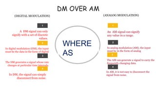
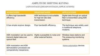
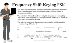
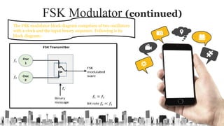
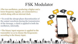
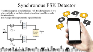
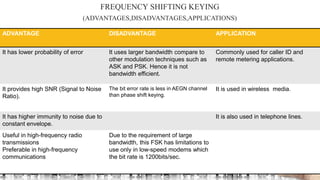
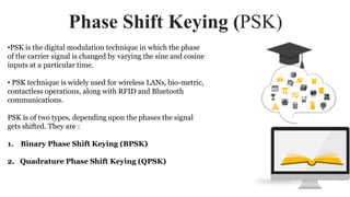
DIGITAL
MODULATION
TECHNIQUES
PREPARED BY:-
SHRIYA GAUTAM
W18DEL1731
http://www.free-powerpoint-templates-design.com
OBJECT
Study the generation and detection
methods of the following digital
modulation techniques : ASK, PSK,
FSK and QPSK.
TOPICS COVERED
1INTRODUCTION
5PSK
6 FSK
4ASK
2ADVANTAGE OF DM OVER AM
3TYPES OF DIGITAL MODULATION
7 QPSK
8
9
10
11
ADVANTAGES
LIMITATIONS
APPLICATION
CONCLUSION
INTRODUCTION
The term DM stands for digital
modulation, and it is a common term for
the techniques of modulation.
Digital modulation is the process of transferring
digital low frequency baseband signal like digital
stream from computer over a high frequency
carrier signal.
With digital modulation technique, the modulation
process corresponds to switching or keying the
amplitude, frequency or phase of the carrier between
either of two possible values corresponding to binary ‘0’
or ‘1’.
DM OVER AM
2
1
3 3
2
1
An AM signal can signify
any value in a range.
In analog modulation (AM), the input
must be in the form of analog
The AM can generate a signal to carry the
frequently changing data.
A DM signal can only
signify with a set of discrete
values.
In digital modulation (DM), the input
must be the data in the form of digital
The DM generates a signal whose rate
changes at particular time intervals.
(DIGITAL MODULATION) (ANALOG MODULATION)
WHERE
AS
4
4
In AM, it is not easy to disconnect the
signal from noise.In DM, the signal can simply
disconnect from noise.
The main advantages of the digital
modulation over analog modulation
include available bandwidth , high
noise immunity and permissible
power. In digital modulation, a
message signal is converted from
analog to digital message, and then
modulated by using a carrier wave.
CONTI
NUED
TYPES OF DIGITAL MODULATION
TECHNIQUES
3
2
1
4
FSK – Frequency Shift
Keying
The frequency of the output
signal will be either high or
low, depending upon the
input data applied.
ASK –Amplitude Shift
Keying
The amplitude of the resultant
output depends upon the input
data whether it should be a
zero level or a variation of
positive and negative,
depending upon the carrier
frequency.
Quadrature Phase Shift Keying (QPSK)
Quadrature Phase Shift Keying (QPSK) is
a form of Phase Shift Keying in which two
bits are modulated at once, selecting one
of four possible carrier phase shifts (0, 90,
180, or 270 degrees).
PSK – Phase Shift
Keying
The phase of the output
signal gets shifted
depending upon the
input.
Amplitude Shift Keying ASK
01
02
03
04
05
ASK is a type of
Amplitude
Modulation
which
represents the
binary data in
the form of
variations in the
amplitude of a
signal.
Any
modulated
signal has a
high
frequency
carrier.
The binary signal
when ASK
modulated, gives
a zero value
for Low input while
it gives the carrier
output for High in
put.
Binary ‘1’ is
represented by
transmitting a
sinusoidal carrier
wave of fixed
amplitude A,
fixed frequency
‘fc’ and fixed
duration Tb
second.
Binary ‘0’ is
represented by
either switching
off the carrier or
transmitting the
same carrier of
frequency ‘fc’ but
with different
amplitude ‘A2’.
The binary ASK may be expressed as:-
ASK Modulator
C E R T I F I C AT E
• The ASK modulator block diagram comprises of the carrier signal
generator, the binary sequence from the message signal and the band-
limited filter. Following is the block diagram of the ASK Modulator.
ASK Modulator(continued)
C E R T I F I C AT E
The carrier generator, sends a continuous high-frequency carrier.
The binary sequence from the message signal makes the unipolar
input to be either High or Low.
When there is low input, the switch opens, allowing
no voltage to appear. Hence, the output will be low.
The band-limiting filter, shapes the pulse
depending upon the amplitude and phase
characteristics of the band-limiting filter or the
pulse-shaping filter.
The high signal closes the switch, allowing a carrier
wave. Hence, the output will be the carrier signal at
high input.
Synchronous ASK Demodulator
C E R T I F I C AT E
• The clock frequency at the transmitter when matches with the clock
frequency at the receiver, it is known as a Synchronous method , as
the frequency gets synchronized.
Synchronous ASK detector consists of a Square law detector, low
pass filter, a comparator, and a voltage limiter. Following is the block
diagram for the same:-
Synchronous ASK Demodulator (continued)
C E R T I F I C AT E
•The ASK modulated input signal is given to the Square
law detector.
• A square law detector is one whose output voltage is
proportional to the square of the amplitude modulated
input voltage.
•The low pass filter minimizes the higher frequencies.
• The comparator and the voltage limiter help to get a
clean digital output.
AMPLITUDE SHIFTING KEYING
(ADVANTAGES,DISADVANTAGES,APPLICATIONS)
ADVANTAGES DISADVANTAGES APPLICATIONS
It offers high bandwidth
efficiency.
ASK technique is not suitable
for high bit rate data
transmission.
Digital data through an optical
fiber is transmitted using ASK
technique.
It has simple receiver design. Poor bandwidth efficiency. The technique was widely used
in traditional telephone
modems.
ASK modulation can be used to
transmit digital data over
optical fiber.
Highly susceptible to noise and
other external factors.
Wireless base stations and
Tire pressuring monitoring
systems
ASK modulation and ASK
demodulation processes are
comparatively inexpensive.
Home automation devices
Frequency Shift Keying FSK
FSK is the digital modulation technique in which the frequency of the carrier
signal varies according to the digital signal changes. FSK is a scheme of
frequency modulation.
The output of a FSK modulated wave is high in frequency for a binary High
input and is low in frequency for a binary Low input. The binary 1s and 0s are
called Mark and Space frequencies.
The following image is the diagrammatic representation of FSK modulated
waveform along with its input:-
FSK Modulator (continued)
The FSK modulator block diagram comprises of two oscillators
with a clock and the input binary sequence. Following is its
block diagram:-
FSK Modulator
•The two oscillators, producing a higher and a
lower frequency signals, are connected to a
switch along with an internal clock.
• To avoid the abrupt phase discontinuities of
the output waveform during the transmission
of the message, a clock is applied to both the
oscillators, internally.
• The binary input sequence is applied to the
transmitter so as to choose the frequencies
according to the binary input.
Synchronous FSK Detector
•The block diagram of Synchronous FSK detector consists of two
mixers with local oscillator circuits, two band pass filters and a
decision circuit.
Following is the diagrammatic representation:-
Synchronous FSK Detector (continued)
•The FSK signal input is given to the two
mixers with local oscillator circuits.
• These two are connected to two band pass
filters.
• These combinations act as demodulators and
the decision circuit chooses which output is
more likely and selects it from any one of the
detectors.
• The two signals have a minimum frequency
separation.
ADVANTAGE DISADVANTAGE APPLICATION
It has lower probability of error It uses larger bandwidth compare to
other modulation techniques such as
ASK and PSK. Hence it is not
bandwidth efficient.
Commonly used for caller ID and
remote metering applications.
It provides high SNR (Signal to Noise
Ratio).
The bit error rate is less in AEGN channel
than phase shift keying.
It is used in wireless media.
It has higher immunity to noise due to
constant envelope.
It is also used in telephone lines.
Useful in high-frequency radio
transmissions
Preferable in high-frequency
communications
Due to the requirement of large
bandwidth, this FSK has limitations to
use only in low-speed modems which
the bit rate is 1200bits/sec.
FREQUENCY SHIFTING KEYING
(ADVANTAGES,DISADVANTAGES,APPLICATIONS)
Phase Shift Keying (PSK)
•PSK is the digital modulation technique in which the phase
of the carrier signal is changed by varying the sine and cosine
inputs at a particular time.
• PSK technique is widely used for wireless LANs, bio-metric,
contactless operations, along with RFID and Bluetooth
communications.
PSK is of two types, depending upon the phases the signal
gets shifted. They are :
1. Binary Phase Shift Keying (BPSK)
2. Quadrature Phase Shift Keying (QPSK)
Binary Phase Shift
Keying(BPSK)
This is also called as 2-phase PSK or Phase Reversal Keying.
In this technique, the sine wave carrier takes two phase
reversals such as 0° and 180°.
BPSK is basically a Double Side Band Suppressed
Carrier (DSBSC) modulation scheme, for message being the
digital information.
BPSK Modulator
The block diagram of Binary Phase Shift Keying consists of the balance
modulator which has the carrier sine wave as one input and the binary sequence
as the other input. Following is the diagrammatic representation:-
BPSK Modulator(continued)
The modulation of BPSK is done using a balance modulator, which multiplies the
two signals applied at the input. For a zero binary input, the phase will be 0° and
for a high input, the phase reversal is of 180°.
Following is the diagrammatic representation of BPSK Modulated
output wave along with its given input:-
The output sine
wave of the
modulator will be
the direct input
carrier or the
inverted 180°phase
Shifted 180°phase
shifted input
carrier, which is a
function of the
data signal.
BPSK Wave when carrier is Sine wave BPSK Wave when carrier is Cosine wave
BPSK Demodulator
The block diagram of BPSK demodulator consists of a mixer with local oscillator circuit,
a bandpass filter, a two-input detector circuit. The diagram is as follows:-
•By recovering the band-limited message signal, with the
help of the mixer circuit and the band pass filter, the first
stage of demodulation gets completed. The base band
signal which is band limited is obtained and this signal is
used to regenerate the binary message bit stream.
•In the next stage of demodulation, the bit clock rate is
needed at the detector circuit to produce the original
binary message signal. If the bit rate is a sub-multiple of
the carrier frequency, then the bit clock regeneration is
simplified. To make the circuit easily understandable, a
decision-making circuit may also be inserted at the
2nd stage of detection.
Quadrature Phase Shift Keying (QPSK)
QPSK is a form of modulation scheme in which two bits are
modulated at once, selecting one of the four possible carrier phase
shift.
It is a particularly interesting one because it actually transmits two
bits per symbol. In other words, a QPSK symbol doesn’t represent 0 or
1—it represents 00, 01, 10, or 11.
QPSK allows the signal to carry twice as much information as
ordinary PSK using the same bandwidth.
In QPSK as with BPSK information carried by transmitted signal is
contained in the phase of the carrier wave.
In particular, the phase of the carrier takes one of the
four equally spaced value such as 𝜋/4, 3𝜋/4, 5𝜋/4, 7𝜋/4 .
QPSK Modulator
The QPSK Modulator uses a bit-splitter, two multipliers with local oscillator, a 2-bit serial to parallel converter
and a summer circuit. Following is the block diagram for the same:-
𝟎𝟎→−𝑽𝑽
𝟏𝟏→+𝑽𝑽
01110010
Cos(𝟐𝝅𝒇𝒄𝒕)
sin (𝟐𝝅𝒇𝒄𝒕)
90o phase shifter
MODULATED OUTPUT WAVEFORM
QPSK Modulator(continued)
•Fig. shows a block diagram of QPSK transmitter. The incoming binary
data sequence is first tranformed into polar form by NRZ level
encoder.
•The symbol ‘1’and ‘0 are represented by ‘+V’ and ‘-V’ respectively.
•At the modulator’s input, the message signal’s even bits (i.e., 2nd bit,
4th bit, 6th bit, etc.) and odd bits (i.e., 1st bit, 3rd bit, 5th bit, etc.) are
separated by the bits splitter and are multiplied with the same carrier
to generate odd BPSK (called as PSKi) and even BPSK (called as
PSKq). The PSKQ signal is anyhow phase shifted by 90° before being
modulated.
•Finally the two PSK signals are added to produce the desired QPSK
signal.
QPSK Demodulator
The QPSK Demodulator uses two product demodulator circuits with local
oscillator, two band pass filters, two integrator circuits, and a 2-bit parallel to
serial converter. Following is the diagram for the same:-
The two product detectors at the input of demodulator simultaneously
demodulate the two BPSK signals. The pair of bits are recovered here from the
original data. These signals after processing, are passed to the parallel to serial
converter.
PHASE SHIFTING KEYING
(ADVANTAGES,DISADVANTAGES,APPLICATIONS)
ADVANTAGE DISADVANTAGE APPLICATIONS
This type of PSK allows information to
be carried with a radio
communications signal more
efficiently compare with FSK.
The bandwidth efficiency of this PSK
is less compared with ASK type of
modulation
This method is broadly used for bio-
metric, wireless LAN along
with wireless communications like
Bluetooth and RFID.
QPSK is another kind of data
transmits wherever 4 phase states are
utilized, all in 90 degrees of one
another.
By estimating the phase states of the
signal, the binary information can be
decoded. Algorithms like recovery and
detection are extremely difficult.
Local Oscillator
Optical Communications
It is less vulnerable to faults when we
evaluate with ASK modulation &
occupies similar bandwidth like ASK.
High-level PSK modulations like
QPSK is more sensitive to phase
differences.
Multi-channel WDM
Delay & add demodulator
It is a non-coherent reference signal Nonlinear effects for WDM
transmission
CONCLUSION
(DIFFERENCE BETWEEN ASK,FSK,PSK)
PARAMETER ASK FSK PSK
Variable characteristics Amplitude Frequency Phase
Bandwidth Is proportional to signal rate
(B =(1+d)S),d is due to
modulation & filtering ,lies
between 0 & 1.
B=(1+d)×S+2Δf B=(1+d)×S
Noise immunity low High High
Complexity Simple Moderately complex Very complex
Error probability High Low Low
Performance in presence of
noise
Poor Better than ASK Better than FSK
Bit rate Suitable upto 100 bits/sec Suitable upto about 1200
bits/sec
Suitable for high bit rates
THANK YOU
FOR YOUR ATTENTION

Digital modulation techniques

  • 1.
  • 2.
    OBJECT Study the generationand detection methods of the following digital modulation techniques : ASK, PSK, FSK and QPSK.
  • 3.
    TOPICS COVERED 1INTRODUCTION 5PSK 6 FSK 4ASK 2ADVANTAGEOF DM OVER AM 3TYPES OF DIGITAL MODULATION 7 QPSK 8 9 10 11 ADVANTAGES LIMITATIONS APPLICATION CONCLUSION
  • 4.
    INTRODUCTION The term DMstands for digital modulation, and it is a common term for the techniques of modulation. Digital modulation is the process of transferring digital low frequency baseband signal like digital stream from computer over a high frequency carrier signal. With digital modulation technique, the modulation process corresponds to switching or keying the amplitude, frequency or phase of the carrier between either of two possible values corresponding to binary ‘0’ or ‘1’.
  • 5.
    DM OVER AM 2 1 33 2 1 An AM signal can signify any value in a range. In analog modulation (AM), the input must be in the form of analog The AM can generate a signal to carry the frequently changing data. A DM signal can only signify with a set of discrete values. In digital modulation (DM), the input must be the data in the form of digital The DM generates a signal whose rate changes at particular time intervals. (DIGITAL MODULATION) (ANALOG MODULATION) WHERE AS 4 4 In AM, it is not easy to disconnect the signal from noise.In DM, the signal can simply disconnect from noise.
  • 6.
    The main advantagesof the digital modulation over analog modulation include available bandwidth , high noise immunity and permissible power. In digital modulation, a message signal is converted from analog to digital message, and then modulated by using a carrier wave. CONTI NUED
  • 7.
    TYPES OF DIGITALMODULATION TECHNIQUES 3 2 1 4 FSK – Frequency Shift Keying The frequency of the output signal will be either high or low, depending upon the input data applied. ASK –Amplitude Shift Keying The amplitude of the resultant output depends upon the input data whether it should be a zero level or a variation of positive and negative, depending upon the carrier frequency. Quadrature Phase Shift Keying (QPSK) Quadrature Phase Shift Keying (QPSK) is a form of Phase Shift Keying in which two bits are modulated at once, selecting one of four possible carrier phase shifts (0, 90, 180, or 270 degrees). PSK – Phase Shift Keying The phase of the output signal gets shifted depending upon the input.
  • 8.
    Amplitude Shift KeyingASK 01 02 03 04 05 ASK is a type of Amplitude Modulation which represents the binary data in the form of variations in the amplitude of a signal. Any modulated signal has a high frequency carrier. The binary signal when ASK modulated, gives a zero value for Low input while it gives the carrier output for High in put. Binary ‘1’ is represented by transmitting a sinusoidal carrier wave of fixed amplitude A, fixed frequency ‘fc’ and fixed duration Tb second. Binary ‘0’ is represented by either switching off the carrier or transmitting the same carrier of frequency ‘fc’ but with different amplitude ‘A2’.
  • 9.
    The binary ASKmay be expressed as:-
  • 10.
    ASK Modulator C ER T I F I C AT E • The ASK modulator block diagram comprises of the carrier signal generator, the binary sequence from the message signal and the band- limited filter. Following is the block diagram of the ASK Modulator.
  • 11.
    ASK Modulator(continued) C ER T I F I C AT E The carrier generator, sends a continuous high-frequency carrier. The binary sequence from the message signal makes the unipolar input to be either High or Low. When there is low input, the switch opens, allowing no voltage to appear. Hence, the output will be low. The band-limiting filter, shapes the pulse depending upon the amplitude and phase characteristics of the band-limiting filter or the pulse-shaping filter. The high signal closes the switch, allowing a carrier wave. Hence, the output will be the carrier signal at high input.
  • 12.
    Synchronous ASK Demodulator CE R T I F I C AT E • The clock frequency at the transmitter when matches with the clock frequency at the receiver, it is known as a Synchronous method , as the frequency gets synchronized. Synchronous ASK detector consists of a Square law detector, low pass filter, a comparator, and a voltage limiter. Following is the block diagram for the same:-
  • 13.
    Synchronous ASK Demodulator(continued) C E R T I F I C AT E •The ASK modulated input signal is given to the Square law detector. • A square law detector is one whose output voltage is proportional to the square of the amplitude modulated input voltage. •The low pass filter minimizes the higher frequencies. • The comparator and the voltage limiter help to get a clean digital output.
  • 14.
    AMPLITUDE SHIFTING KEYING (ADVANTAGES,DISADVANTAGES,APPLICATIONS) ADVANTAGESDISADVANTAGES APPLICATIONS It offers high bandwidth efficiency. ASK technique is not suitable for high bit rate data transmission. Digital data through an optical fiber is transmitted using ASK technique. It has simple receiver design. Poor bandwidth efficiency. The technique was widely used in traditional telephone modems. ASK modulation can be used to transmit digital data over optical fiber. Highly susceptible to noise and other external factors. Wireless base stations and Tire pressuring monitoring systems ASK modulation and ASK demodulation processes are comparatively inexpensive. Home automation devices
  • 15.
    Frequency Shift KeyingFSK FSK is the digital modulation technique in which the frequency of the carrier signal varies according to the digital signal changes. FSK is a scheme of frequency modulation. The output of a FSK modulated wave is high in frequency for a binary High input and is low in frequency for a binary Low input. The binary 1s and 0s are called Mark and Space frequencies. The following image is the diagrammatic representation of FSK modulated waveform along with its input:-
  • 16.
    FSK Modulator (continued) TheFSK modulator block diagram comprises of two oscillators with a clock and the input binary sequence. Following is its block diagram:-
  • 17.
    FSK Modulator •The twooscillators, producing a higher and a lower frequency signals, are connected to a switch along with an internal clock. • To avoid the abrupt phase discontinuities of the output waveform during the transmission of the message, a clock is applied to both the oscillators, internally. • The binary input sequence is applied to the transmitter so as to choose the frequencies according to the binary input.
  • 18.
    Synchronous FSK Detector •Theblock diagram of Synchronous FSK detector consists of two mixers with local oscillator circuits, two band pass filters and a decision circuit. Following is the diagrammatic representation:-
  • 19.
    Synchronous FSK Detector(continued) •The FSK signal input is given to the two mixers with local oscillator circuits. • These two are connected to two band pass filters. • These combinations act as demodulators and the decision circuit chooses which output is more likely and selects it from any one of the detectors. • The two signals have a minimum frequency separation.
  • 20.
    ADVANTAGE DISADVANTAGE APPLICATION Ithas lower probability of error It uses larger bandwidth compare to other modulation techniques such as ASK and PSK. Hence it is not bandwidth efficient. Commonly used for caller ID and remote metering applications. It provides high SNR (Signal to Noise Ratio). The bit error rate is less in AEGN channel than phase shift keying. It is used in wireless media. It has higher immunity to noise due to constant envelope. It is also used in telephone lines. Useful in high-frequency radio transmissions Preferable in high-frequency communications Due to the requirement of large bandwidth, this FSK has limitations to use only in low-speed modems which the bit rate is 1200bits/sec. FREQUENCY SHIFTING KEYING (ADVANTAGES,DISADVANTAGES,APPLICATIONS)
  • 21.
    Phase Shift Keying(PSK) •PSK is the digital modulation technique in which the phase of the carrier signal is changed by varying the sine and cosine inputs at a particular time. • PSK technique is widely used for wireless LANs, bio-metric, contactless operations, along with RFID and Bluetooth communications. PSK is of two types, depending upon the phases the signal gets shifted. They are : 1. Binary Phase Shift Keying (BPSK) 2. Quadrature Phase Shift Keying (QPSK)
  • 22.
    Binary Phase Shift Keying(BPSK) Thisis also called as 2-phase PSK or Phase Reversal Keying. In this technique, the sine wave carrier takes two phase reversals such as 0° and 180°. BPSK is basically a Double Side Band Suppressed Carrier (DSBSC) modulation scheme, for message being the digital information.
  • 23.
    BPSK Modulator The blockdiagram of Binary Phase Shift Keying consists of the balance modulator which has the carrier sine wave as one input and the binary sequence as the other input. Following is the diagrammatic representation:-
  • 24.
    BPSK Modulator(continued) The modulationof BPSK is done using a balance modulator, which multiplies the two signals applied at the input. For a zero binary input, the phase will be 0° and for a high input, the phase reversal is of 180°. Following is the diagrammatic representation of BPSK Modulated output wave along with its given input:- The output sine wave of the modulator will be the direct input carrier or the inverted 180°phase Shifted 180°phase shifted input carrier, which is a function of the data signal.
  • 25.
    BPSK Wave whencarrier is Sine wave BPSK Wave when carrier is Cosine wave
  • 26.
    BPSK Demodulator The blockdiagram of BPSK demodulator consists of a mixer with local oscillator circuit, a bandpass filter, a two-input detector circuit. The diagram is as follows:- •By recovering the band-limited message signal, with the help of the mixer circuit and the band pass filter, the first stage of demodulation gets completed. The base band signal which is band limited is obtained and this signal is used to regenerate the binary message bit stream. •In the next stage of demodulation, the bit clock rate is needed at the detector circuit to produce the original binary message signal. If the bit rate is a sub-multiple of the carrier frequency, then the bit clock regeneration is simplified. To make the circuit easily understandable, a decision-making circuit may also be inserted at the 2nd stage of detection.
  • 27.
    Quadrature Phase ShiftKeying (QPSK) QPSK is a form of modulation scheme in which two bits are modulated at once, selecting one of the four possible carrier phase shift. It is a particularly interesting one because it actually transmits two bits per symbol. In other words, a QPSK symbol doesn’t represent 0 or 1—it represents 00, 01, 10, or 11. QPSK allows the signal to carry twice as much information as ordinary PSK using the same bandwidth. In QPSK as with BPSK information carried by transmitted signal is contained in the phase of the carrier wave. In particular, the phase of the carrier takes one of the four equally spaced value such as 𝜋/4, 3𝜋/4, 5𝜋/4, 7𝜋/4 .
  • 28.
    QPSK Modulator The QPSKModulator uses a bit-splitter, two multipliers with local oscillator, a 2-bit serial to parallel converter and a summer circuit. Following is the block diagram for the same:- 𝟎𝟎→−𝑽𝑽 𝟏𝟏→+𝑽𝑽 01110010 Cos(𝟐𝝅𝒇𝒄𝒕) sin (𝟐𝝅𝒇𝒄𝒕) 90o phase shifter MODULATED OUTPUT WAVEFORM
  • 29.
    QPSK Modulator(continued) •Fig. showsa block diagram of QPSK transmitter. The incoming binary data sequence is first tranformed into polar form by NRZ level encoder. •The symbol ‘1’and ‘0 are represented by ‘+V’ and ‘-V’ respectively. •At the modulator’s input, the message signal’s even bits (i.e., 2nd bit, 4th bit, 6th bit, etc.) and odd bits (i.e., 1st bit, 3rd bit, 5th bit, etc.) are separated by the bits splitter and are multiplied with the same carrier to generate odd BPSK (called as PSKi) and even BPSK (called as PSKq). The PSKQ signal is anyhow phase shifted by 90° before being modulated. •Finally the two PSK signals are added to produce the desired QPSK signal.
  • 31.
    QPSK Demodulator The QPSKDemodulator uses two product demodulator circuits with local oscillator, two band pass filters, two integrator circuits, and a 2-bit parallel to serial converter. Following is the diagram for the same:- The two product detectors at the input of demodulator simultaneously demodulate the two BPSK signals. The pair of bits are recovered here from the original data. These signals after processing, are passed to the parallel to serial converter.
  • 32.
    PHASE SHIFTING KEYING (ADVANTAGES,DISADVANTAGES,APPLICATIONS) ADVANTAGEDISADVANTAGE APPLICATIONS This type of PSK allows information to be carried with a radio communications signal more efficiently compare with FSK. The bandwidth efficiency of this PSK is less compared with ASK type of modulation This method is broadly used for bio- metric, wireless LAN along with wireless communications like Bluetooth and RFID. QPSK is another kind of data transmits wherever 4 phase states are utilized, all in 90 degrees of one another. By estimating the phase states of the signal, the binary information can be decoded. Algorithms like recovery and detection are extremely difficult. Local Oscillator Optical Communications It is less vulnerable to faults when we evaluate with ASK modulation & occupies similar bandwidth like ASK. High-level PSK modulations like QPSK is more sensitive to phase differences. Multi-channel WDM Delay & add demodulator It is a non-coherent reference signal Nonlinear effects for WDM transmission
  • 33.
    CONCLUSION (DIFFERENCE BETWEEN ASK,FSK,PSK) PARAMETERASK FSK PSK Variable characteristics Amplitude Frequency Phase Bandwidth Is proportional to signal rate (B =(1+d)S),d is due to modulation & filtering ,lies between 0 & 1. B=(1+d)×S+2Δf B=(1+d)×S Noise immunity low High High Complexity Simple Moderately complex Very complex Error probability High Low Low Performance in presence of noise Poor Better than ASK Better than FSK Bit rate Suitable upto 100 bits/sec Suitable upto about 1200 bits/sec Suitable for high bit rates
  • 34.

Editor's Notes

  • #5 https://www.elprocus.com/digital-modulation-different-types-and-their-differences/
  • #6 https://www.elprocus.com/digital-modulation-different-types-and-their-differences/
  • #7 https://www.watelectronics.com/types-of-modulation-techniques-with-applications/#:~:text=The%20main%20advantages%20of%20the,by%20using%20a%20carrier%20wave.
  • #8  For QPSK:-https://www.maximintegrated.com/en/glossary/definitions.mvp/term/QPSK/gpk/244#:~:text=Quadrature%20Phase%20Shift%20Keying%20(QPSK,PSK%20using%20the%20same%20bandwidth. AND SOME FROM YOUR LAST SEMESTER NOTES.
  • #9 https://www.tutorialspoint.com/digital_communication/digital_communication_amplitude_shift_keying.htm AND FROM YOUR LAST SEMESTER NOTES
  • #11 https://www.tutorialspoint.com/digital_communication/digital_communication_amplitude_shift_keying.htm
  • #12 https://www.tutorialspoint.com/digital_communication/digital_communication_amplitude_shift_keying.htm
  • #13 https://www.tutorialspoint.com/digital_communication/digital_communication_amplitude_shift_keying.htm
  • #14 https://www.tutorialspoint.com/digital_communication/digital_communication_amplitude_shift_keying.htm
  • #15 1- https://www.rfwireless-world.com/Terminology/Advantages-and-Disadvantages-of-ASK.html#:~:text=Disadvantages%20of%20ASK%20modulation,-Following%20are%20the&text=%E2%9E%A8ASK%20modulation%20is%20very,error%20than%20ASK%20is%20used. 2- https://www.elprocus.com/amplitude-shift-keying-ask-working-and-applications/
  • #16 https://www.tutorialspoint.com/digital_communication/digital_communication_frequency_shift_keying.htm
  • #17 https://www.tutorialspoint.com/digital_communication/digital_communication_frequency_shift_keying.htm
  • #18 https://www.tutorialspoint.com/digital_communication/digital_communication_frequency_shift_keying.htm
  • #19 https://www.tutorialspoint.com/digital_communication/digital_communication_frequency_shift_keying.htm
  • #20 https://www.tutorialspoint.com/digital_communication/digital_communication_frequency_shift_keying.htm
  • #21 1- https://www.rfwireless-world.com/Terminology/Advantages-and-Disadvantages-of-FSK.html#:~:text=Following%20are%20the%20benefits%20or,noise%20due%20to%20constant%20envelope. 2- https://www.elprocus.com/frequency-shift-keying-fsk-working-applications/
  • #22 https://www.tutorialspoint.com/digital_communication/digital_communication_phase_shift_keying.htm
  • #23 https://www.tutorialspoint.com/digital_communication/digital_communication_phase_shift_keying.htm
  • #24 https://www.tutorialspoint.com/digital_communication/digital_communication_phase_shift_keying.htm
  • #25 https://www.tutorialspoint.com/digital_communication/digital_communication_phase_shift_keying.htm
  • #26 FROM LAST SEMESTER NOTES
  • #27 https://www.tutorialspoint.com/digital_communication/digital_communication_phase_shift_keying.htm
  • #28 https://www.tutorialspoint.com/digital_communication/digital_communication_phase_shift_keying.htm
  • #29 https://www.tutorialspoint.com/digital_communication/digital_communication_phase_shift_keying.htm
  • #30 https://www.tutorialspoint.com/digital_communication/digital_communication_phase_shift_keying.htm
  • #32 https://www.tutorialspoint.com/digital_communication/digital_communication_frequency_shift_keying.htm
  • #33 https://www.elprocus.com/phase-shift-keying-psk-types-and-its-applications/
  • #34 https://www.ques10.com/p/3619/compare-ask-psk-fsk-systems-1/