This document provides a 3-paragraph summary of the key concepts of fiber optics:
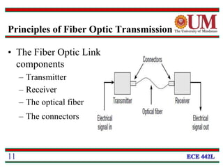
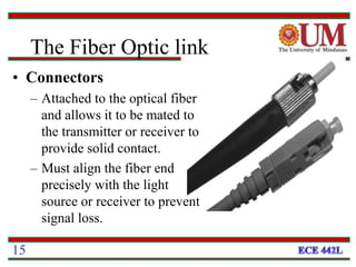
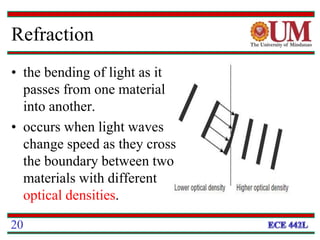
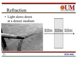
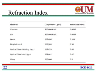
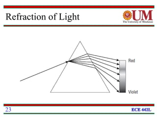
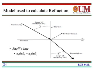
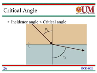
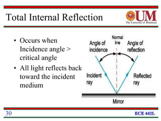
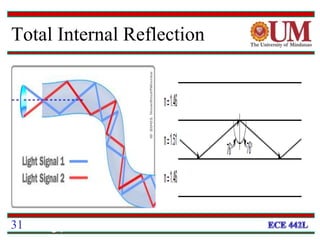
Fiber optics uses glass or plastic fibers to guide light along its length through the process of total internal reflection. Light is transmitted from a transmitter that converts an electrical signal to light, through the fiber, and received at the other end by a receiver that converts the light back to an electrical signal. Refraction causes light to bend as it passes between materials with different refractive indices, and total internal reflection keeps light confined within the fiber when it encounters a change in index of refraction at the fiber's outer surface.