Downloaded 2,608 times
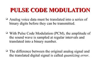
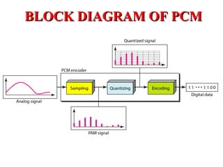


The document outlines Pulse Code Modulation (PCM), detailing its processes including filtering, sampling, quantization, and encoding. It discusses the advantages and disadvantages of PCM, such as its uniform quality and high bandwidth requirement, and differentiates between European and American PCM standards. Applications of PCM include digital audio and telephony, highlighting its importance in modern digital communication systems.