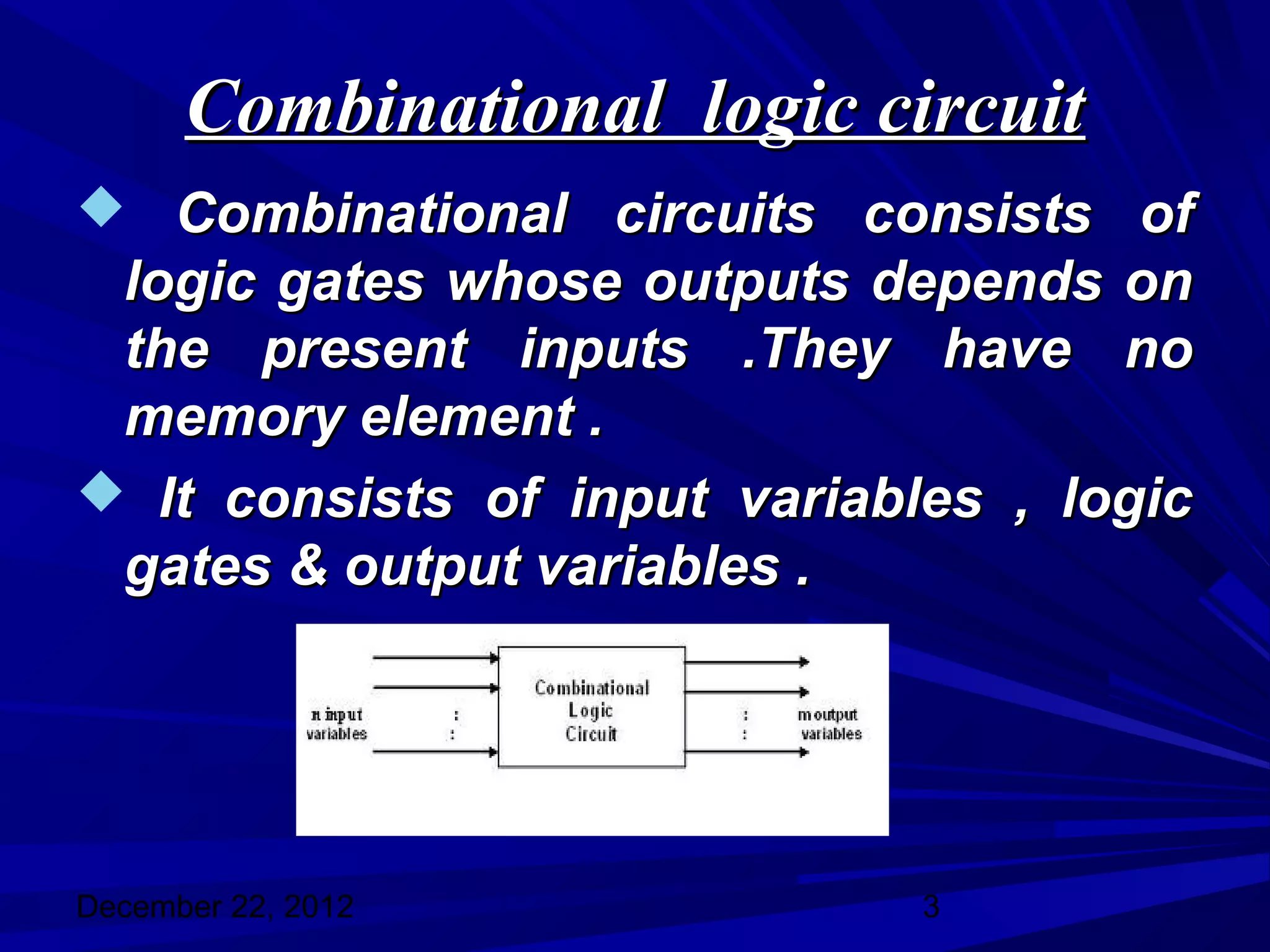
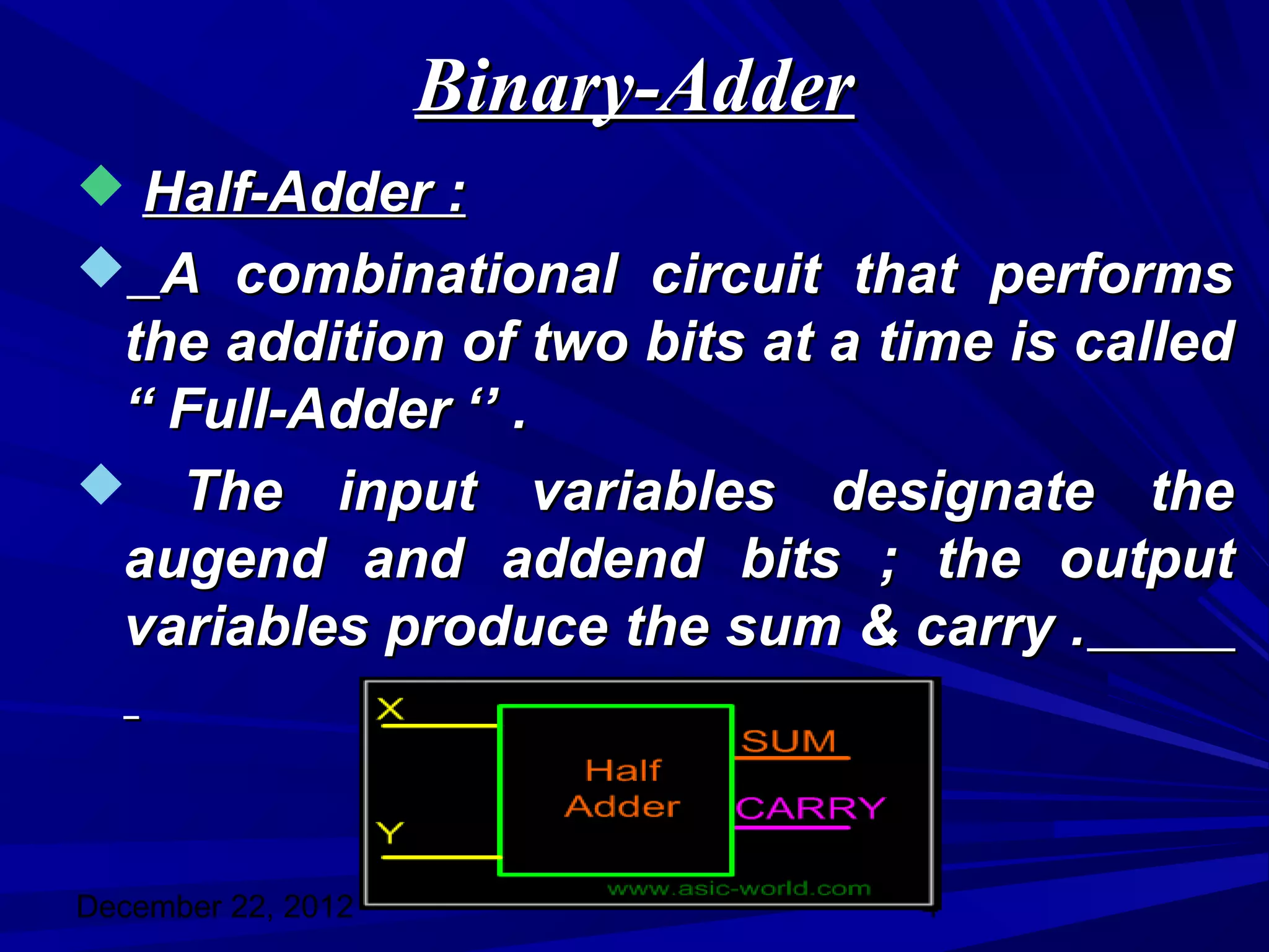
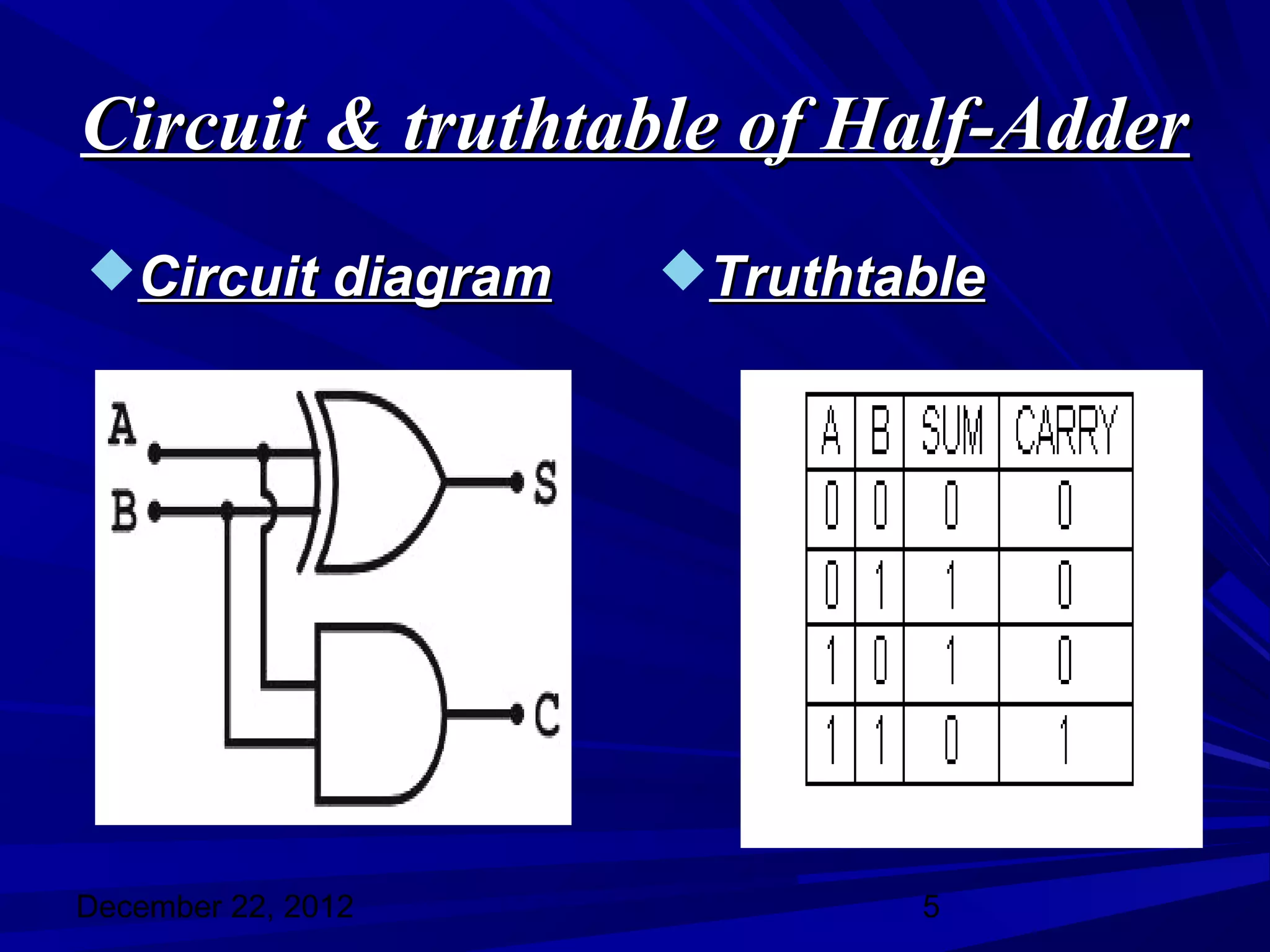
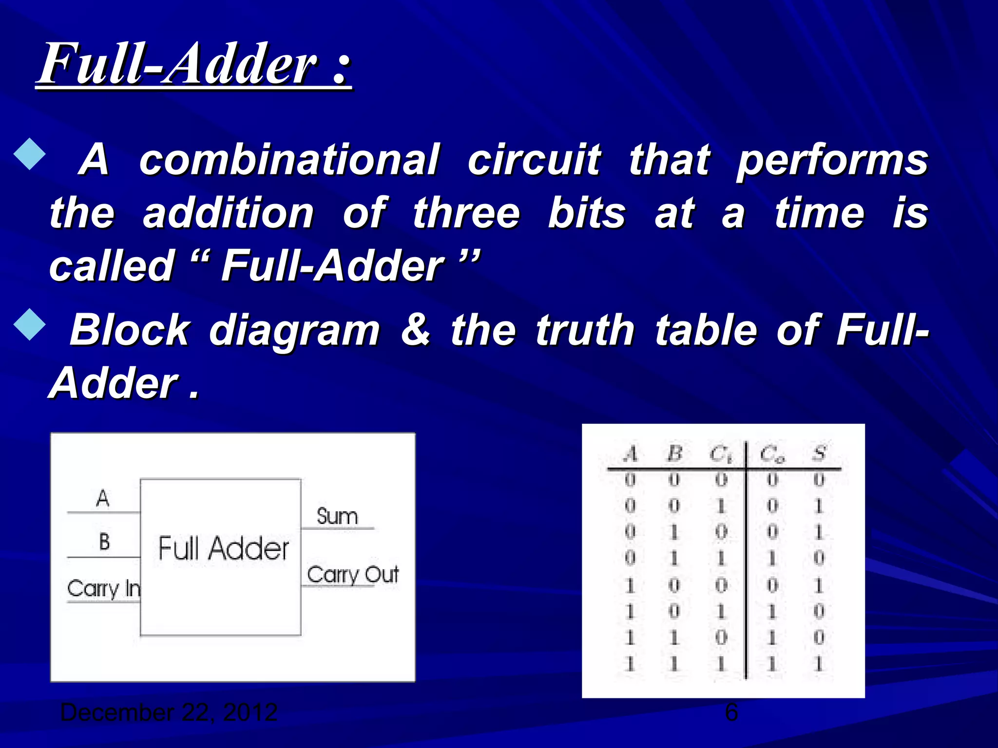
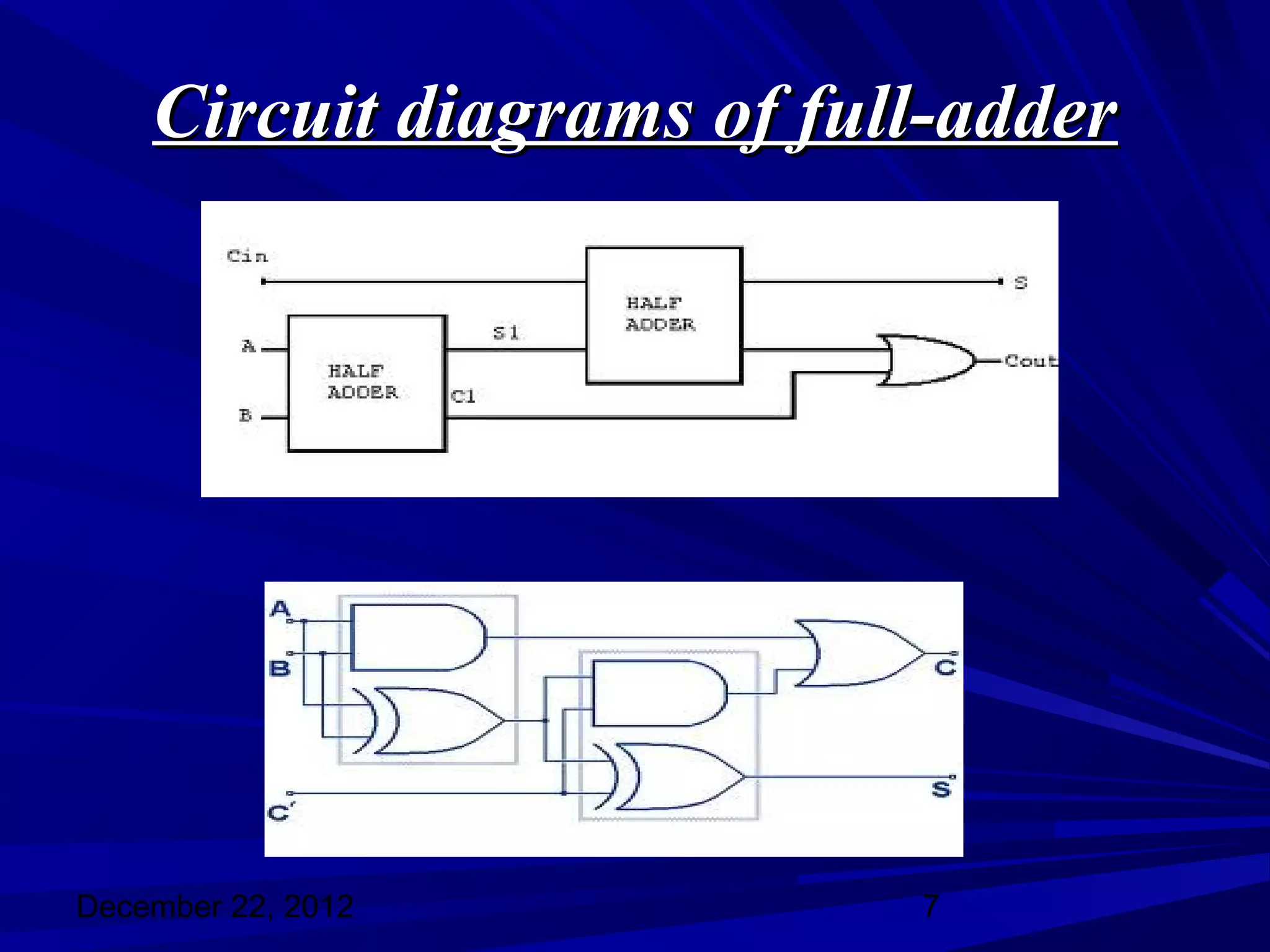
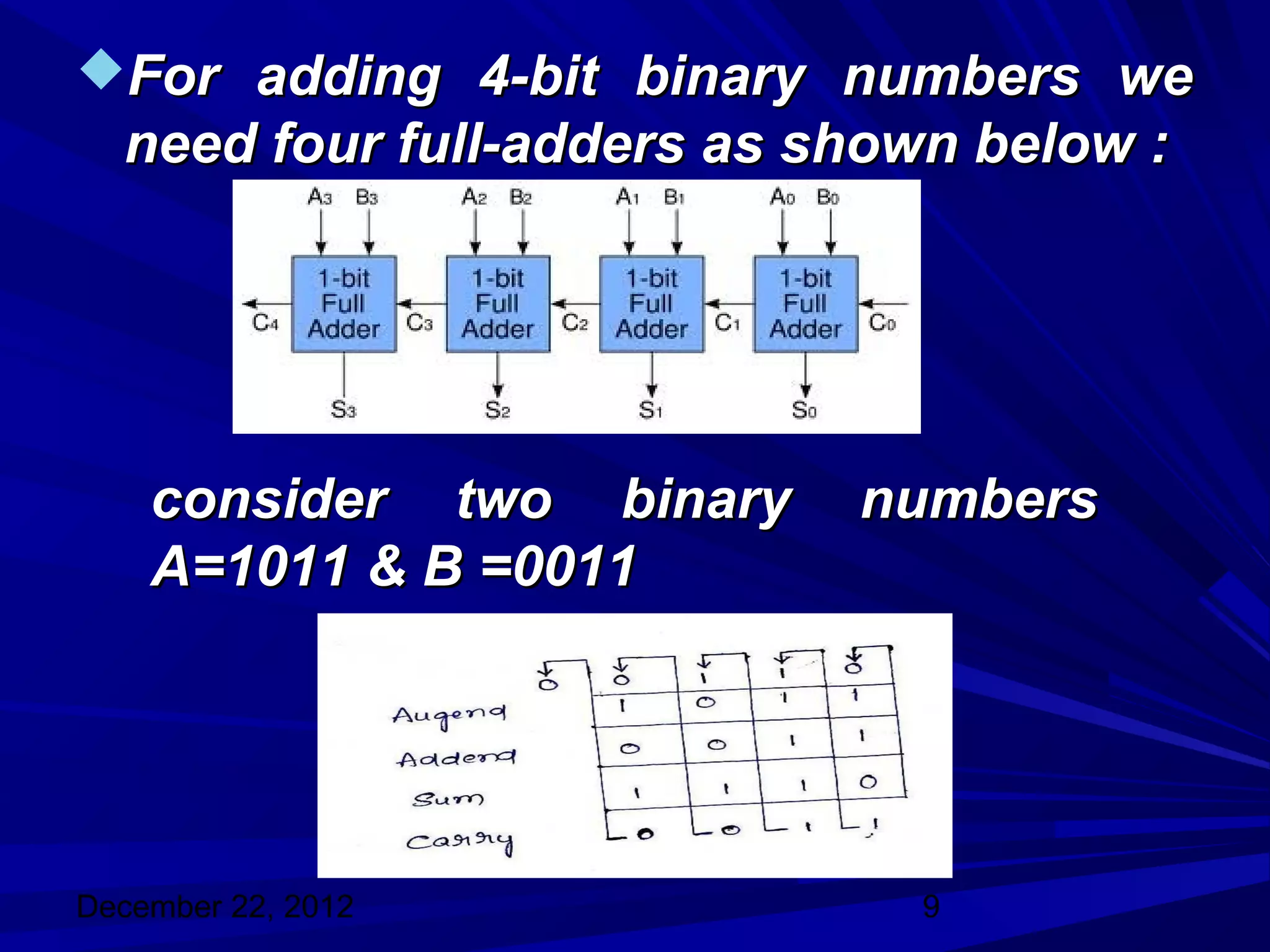
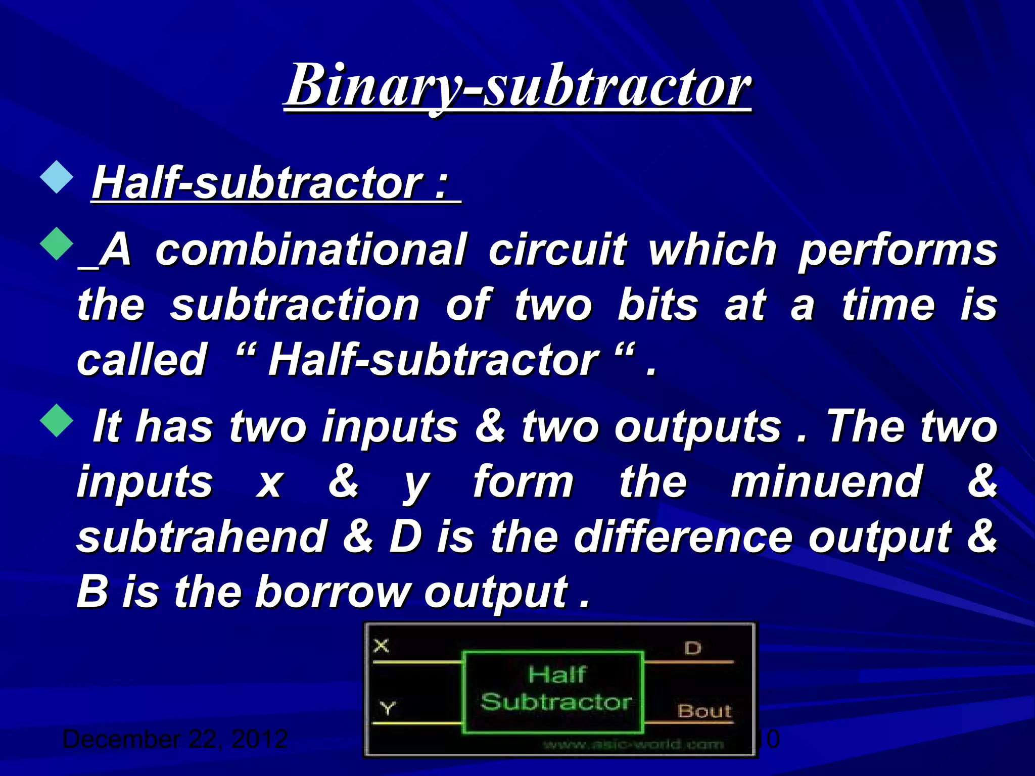
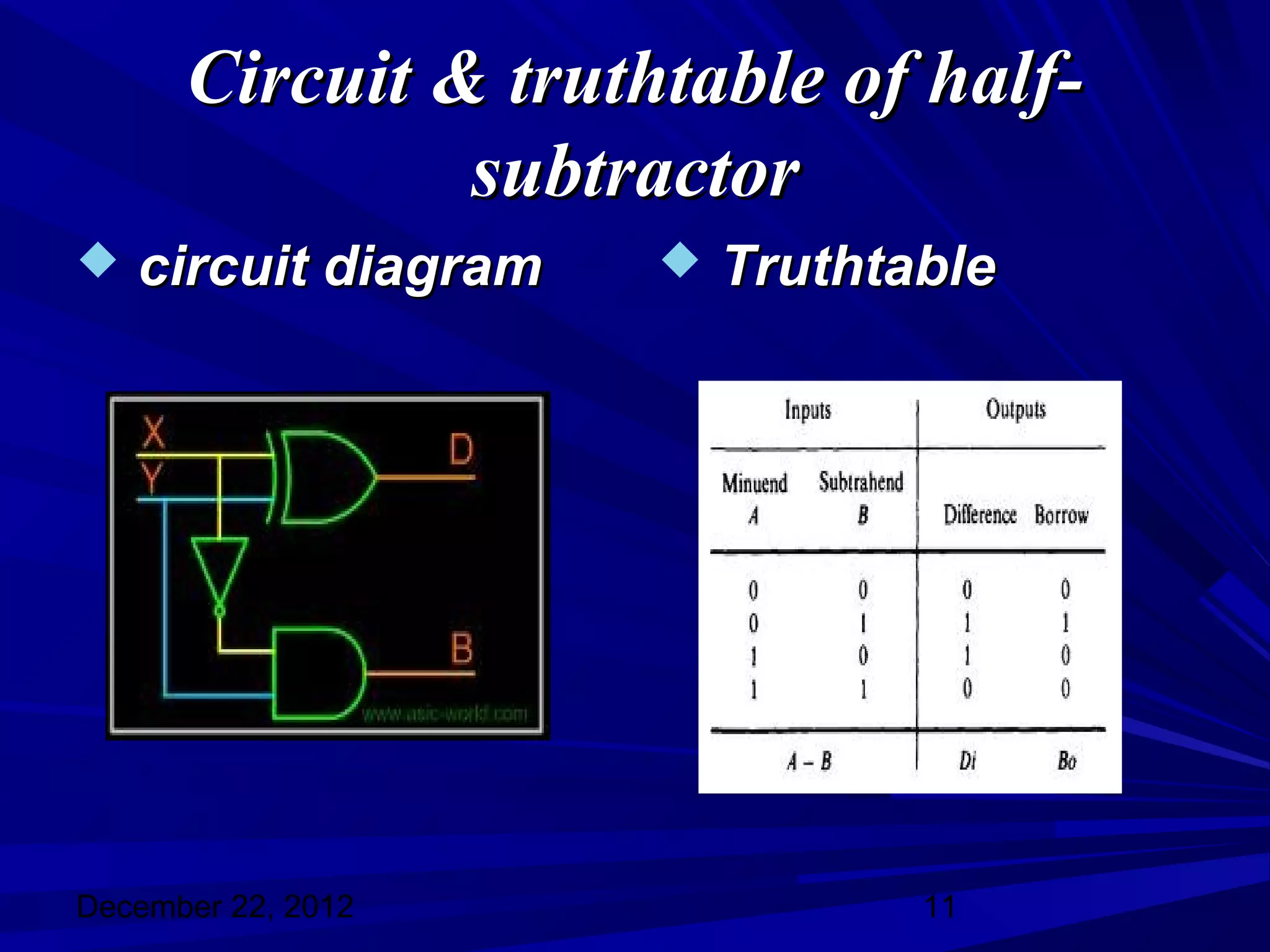
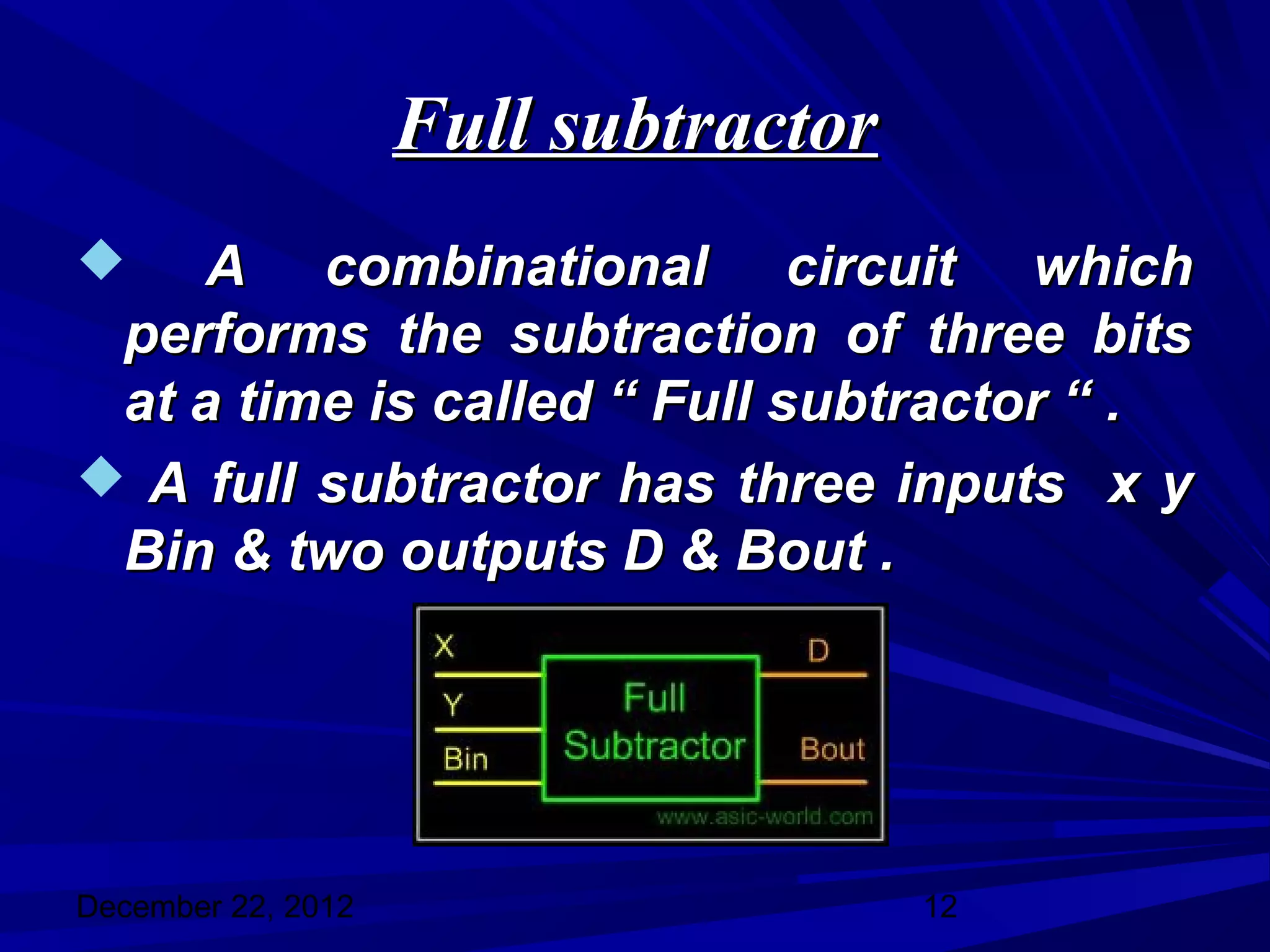
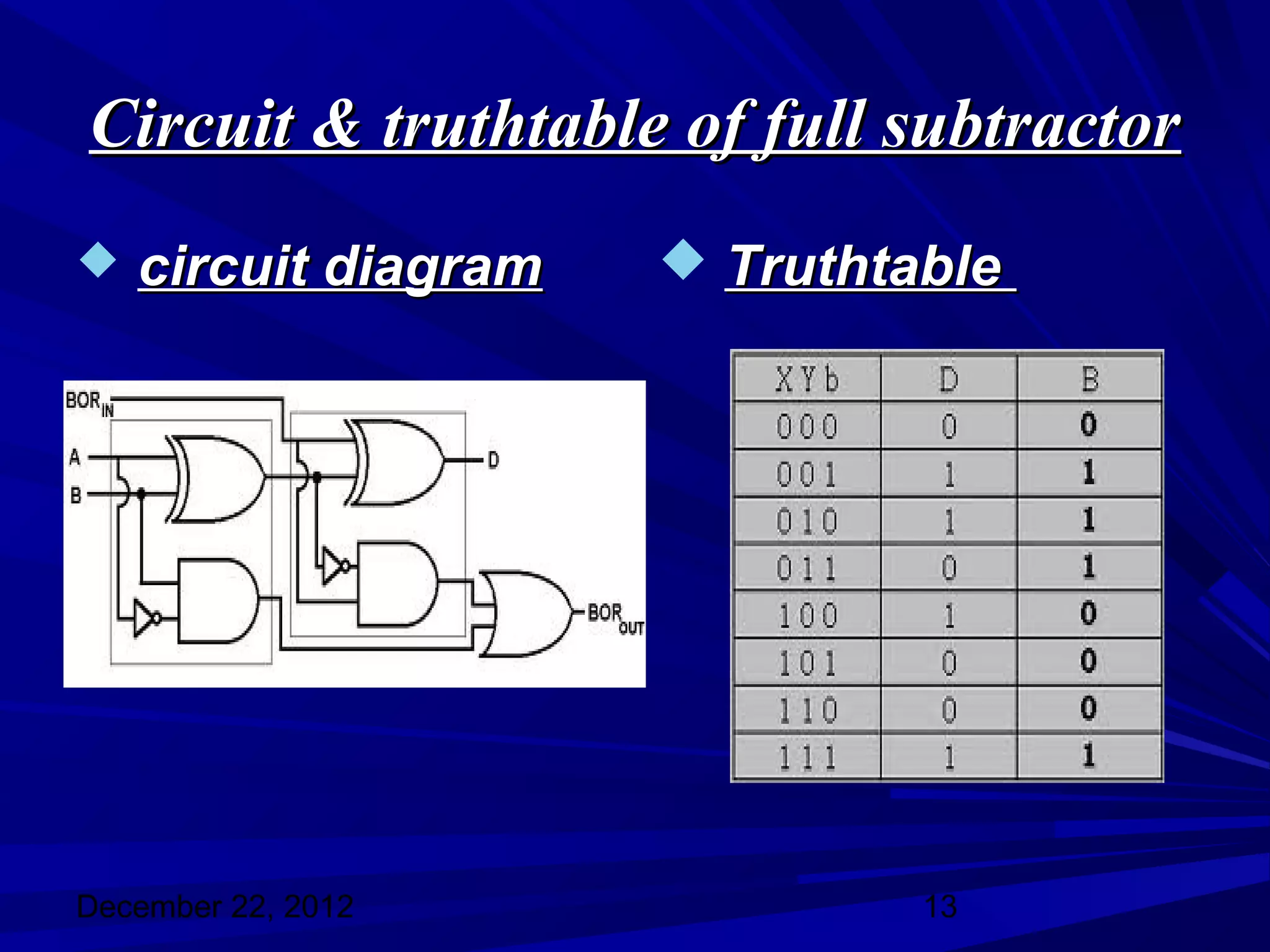
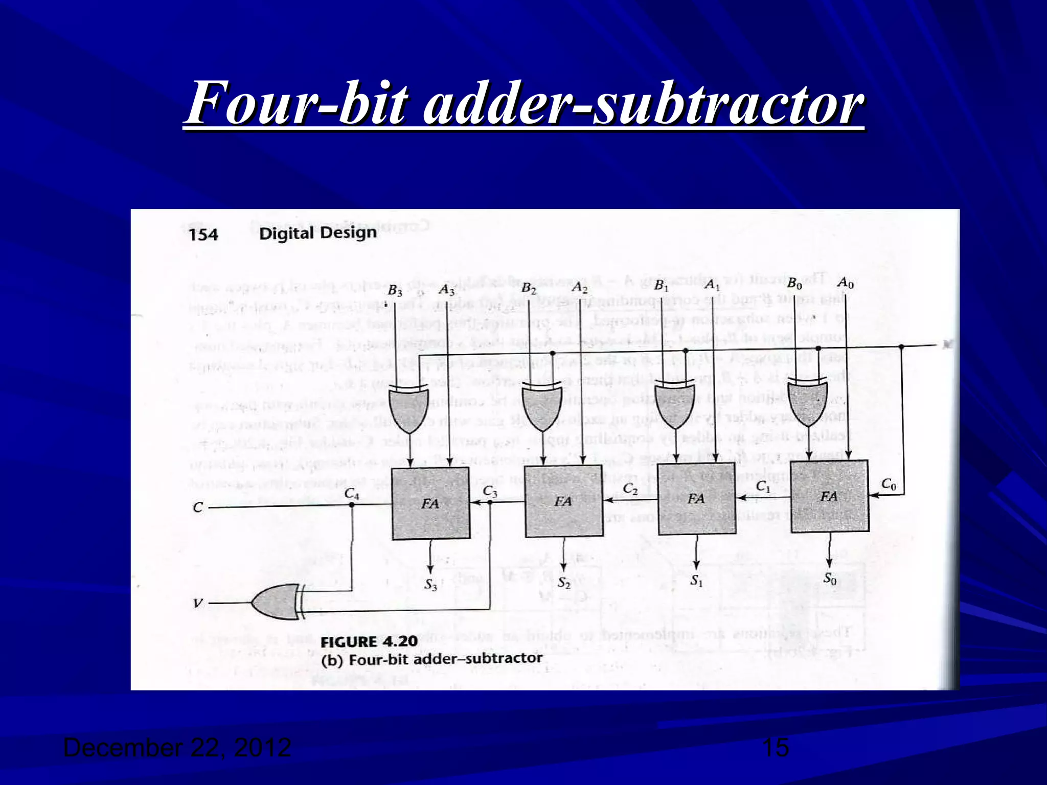
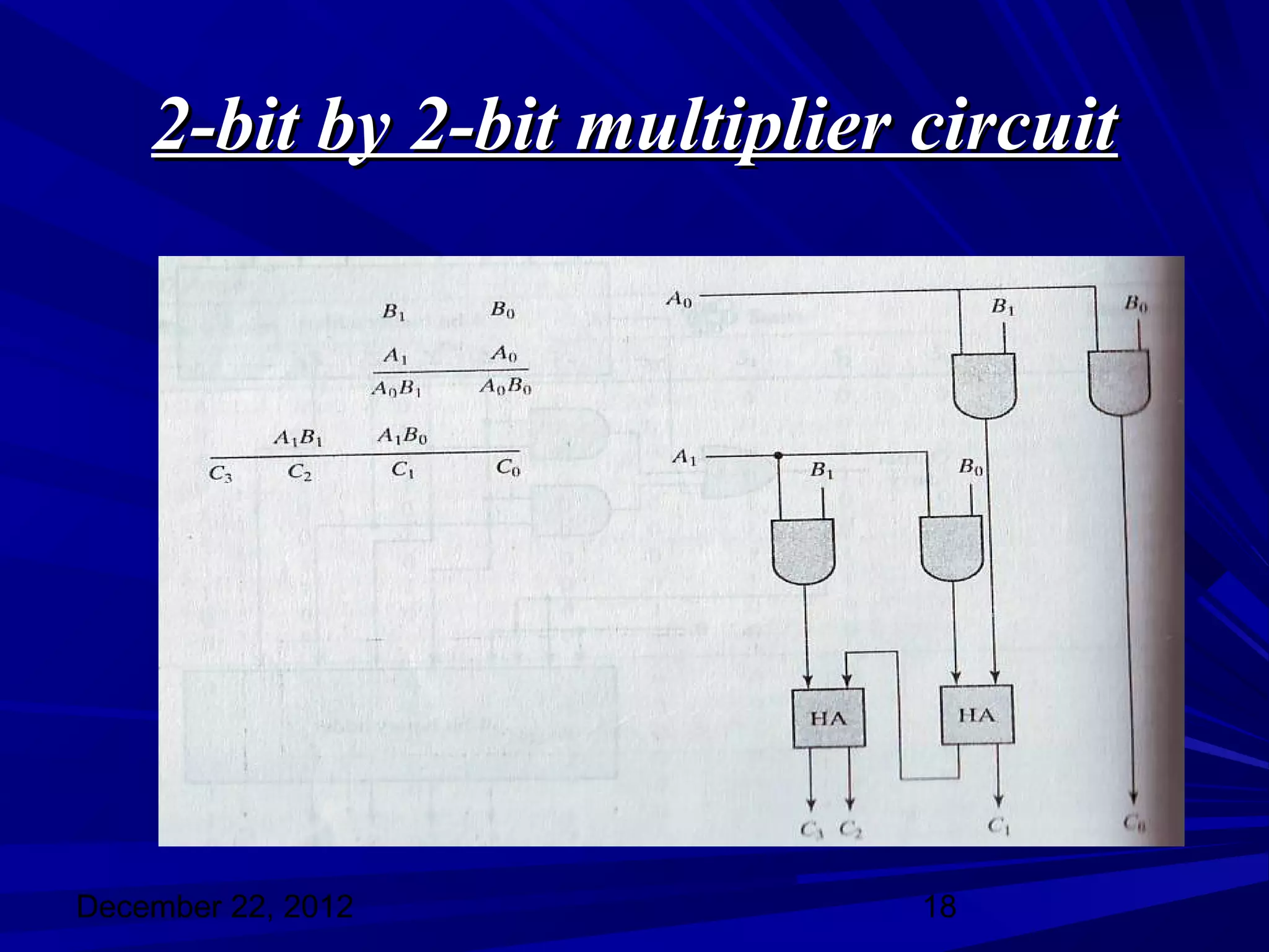
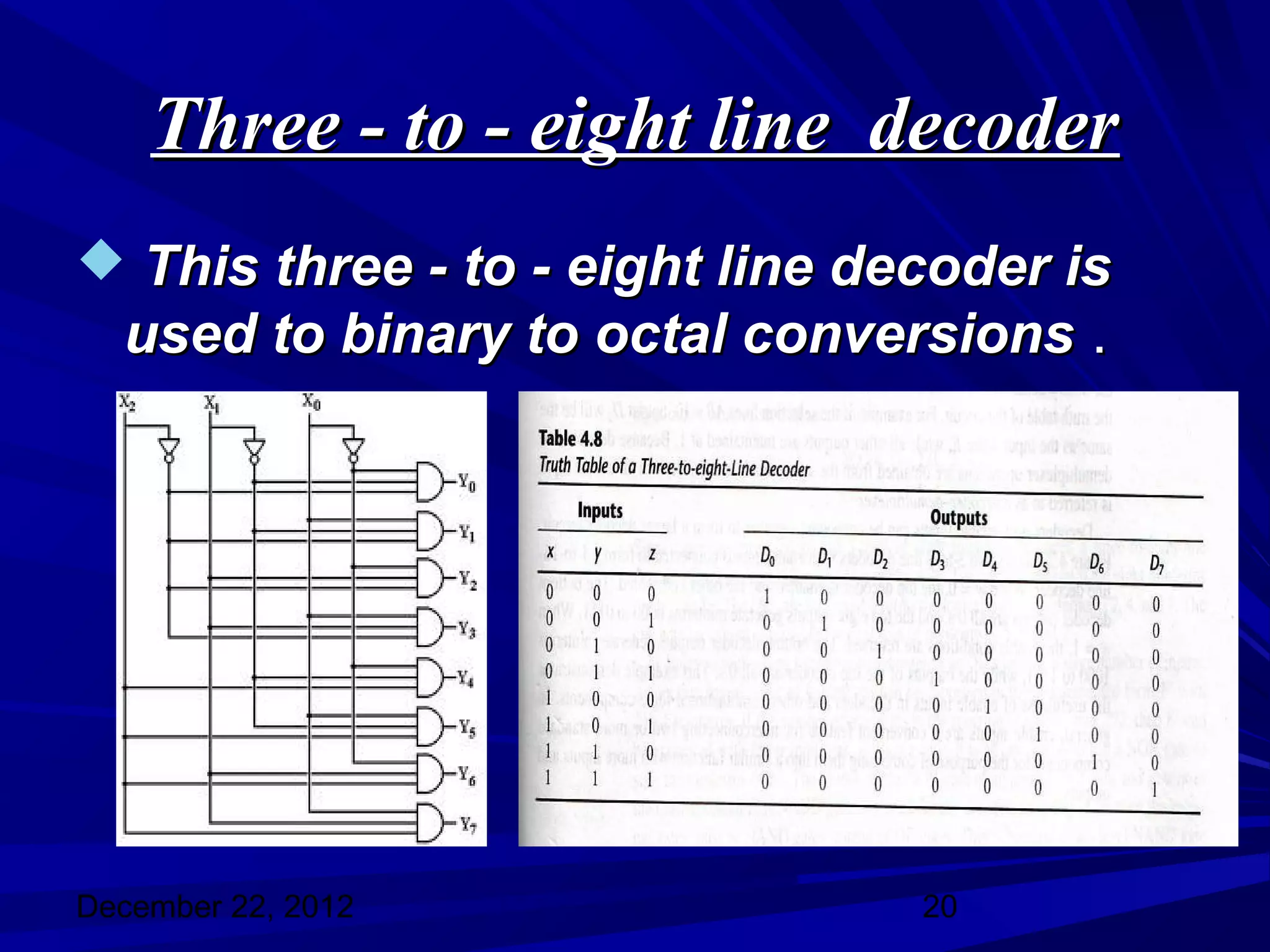
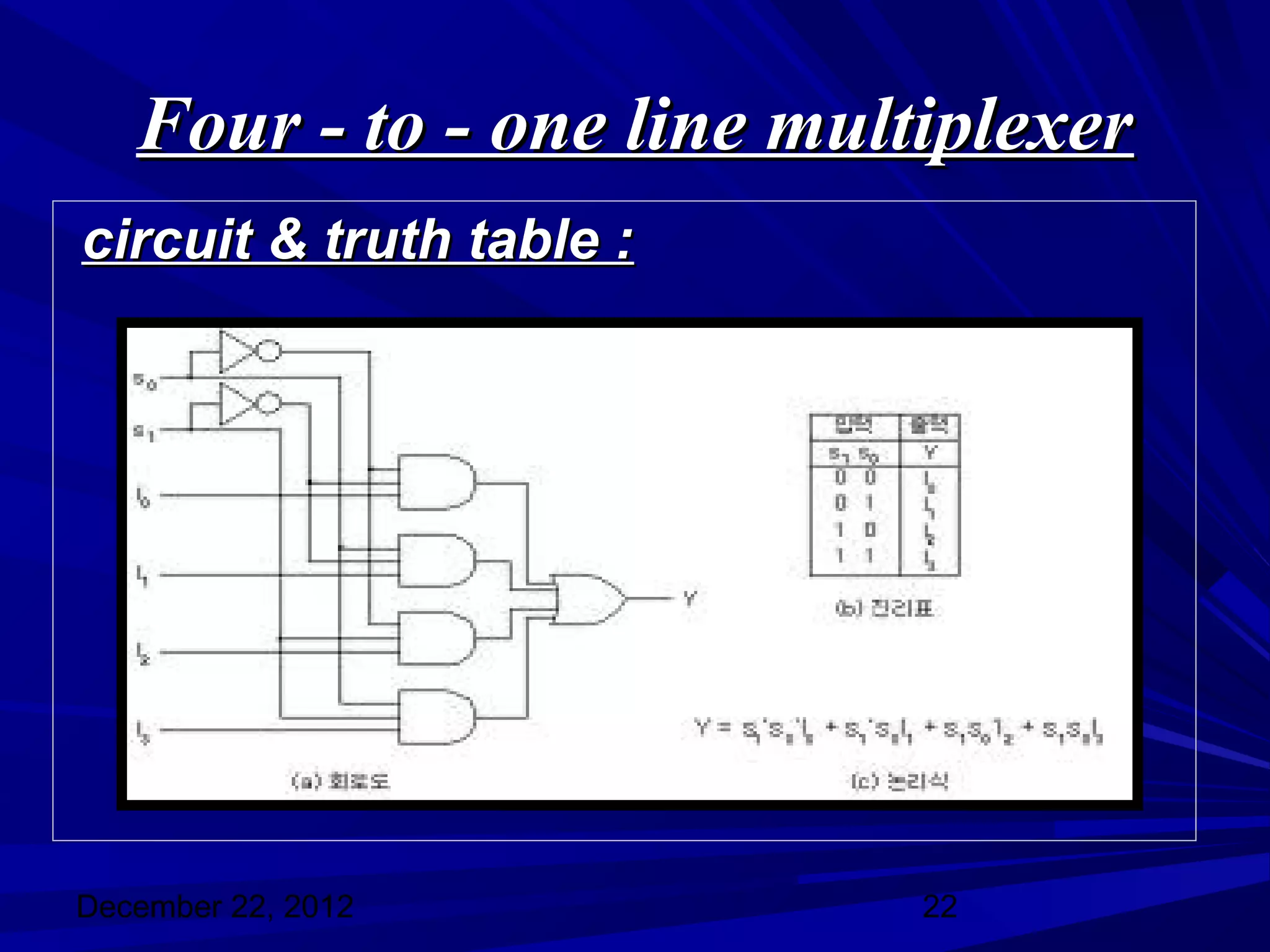
This document discusses combinational logic circuits such as adders, subtractors, multipliers, decoders, and multiplexers. It provides circuit diagrams and truth tables for half adders, full adders, half subtractors, full subtractors, decoders, and multiplexers. It also describes how to build binary adders and subtractors using these basic components and how multiplication of binary numbers is performed.
In which i describe all the features of decoder. All the functionalities describe with the circuits and truth tables. So download and learn more about decoder. Decoder Full Presentation.
1. Combinational logic circuits
Dr. C. Saritha
Lecturer in Electronics
SSBN Degree and PG College
Anantapur
December 22, 2012 1
2. overview
What is combinational logic circuit ?
Examples of combinational logic
circuits
Binary-adder
Binary-subtractor
Binary-multiplier
Decoders
Multiplexers
December 22, 2012 2
3. Combinational logic circuit
Combinational circuits consists of
logic gates whose outputs depends on
the present inputs .They have no
memory element .
It consists of input variables , logic
gates & output variables .
December 22, 2012 3
4. Binary-Adder
Half-Adder :
A combinational circuit that performs
the addition of two bits at a time is called
“ Full-Adder ‘’ .
The input variables designate the
augend and addend bits ; the output
variables produce the sum & carry .
December 22, 2012 4
5. Circuit & truthtable of Half-Adder
Circuit diagram Truthtable
December 22, 2012 5
6. Full-Adder :
A combinational circuit that performs
the addition of three bits at a time is
called “ Full-Adder ’’
Block diagram & the truth table of Full-
Adder .
December 22, 2012 6
8. Binary-Adder
A Binary-Adder is a digital circuit that
produces the arthimatic sum of two
binary numbers at a time .
It can also construct by cascading no
of full-adders we get a N-bit binary-
adder circuit .
An N-bit adder requires n full-adders
with each output carry connected to
the input carry to the next full-adder .
December 22, 2012 8
9. For adding 4-bit binary numbers we
need four full-adders as shown below :
consider two binary numbers
A=1011 & B =0011
December 22, 2012 9
10. Binary-subtractor
Half-subtractor :
A combinational circuit which performs
the subtraction of two bits at a time is
called “ Half-subtractor “ .
It has two inputs & two outputs . The two
inputs x & y form the minuend &
subtrahend & D is the difference output &
B is the borrow output .
December 22, 2012 10
11. Circuit & truthtable of half-
subtractor
circuit diagram Truthtable
December 22, 2012 11
12. Full subtractor
A combinational circuit which
performs the subtraction of three bits
at a time is called “ Full subtractor “ .
A full subtractor has three inputs x y
Bin & two outputs D & Bout .
December 22, 2012 12
13. Circuit & truthtable of full subtractor
circuit diagram Truthtable
December 22, 2012 13
14. Binary-subtractor
The subtraction can be done by taking
the 2’s compliment of B and adding it
to A .
2’s compliment can be obtained by
taking the 1’s compliment and adding 1
to least significant bit .
1’s compliment can be obtained by
changing 1’s into 0’s & 0’s into 1’s .
December 22, 2012 14
16. Continues…..
In this circuit the mode input m
controls the operation . When m=0 , the
circuit is an adder circuit . When m=1,
the circuit becomes a subtractor .
The c & v are two outputs . C is for
carry & v is for overflow . If v=0 after an
addition or subtraction ,then no
overflow occurred and the n-bit result
is correct . If v=1 , then the result of the
operation contains n+1 bits .
December 22, 2012 16
17. Binary-multiplier
The multiplication of binary numbers
is performed in the same way as
multiplication of decimal numbers .
If we take the multiplication of 2-bit
numbers . The multiplicand bits are
B1 & B0 , the multiplier bits are A1 &
A0 and the product is C3,C2,C1,C0 .
December 22, 2012 17
19. Decoders
A decoder is a combinational circuit
that converts binary information from n
input lines to a maximum of 2n unique
output lines .
Generally a decoder is called as n to m
line decoder .
A decoder is used to convert binary
form to any other desired form .
December 22, 2012 19
20. Three - to - eight line decoder
This three - to - eight line decoder is
used to binary to octal conversions .
December 22, 2012 20
21. Multiplexer
multiplexer is a combinational circuit
that selects binary information from
one of many input lines and directs it to
a single output line .
Normally there are 2n input lines and n
selection lines whose bit combinations
determines which input is selected .
A multiplexer is also called ‘ Data
selector ’
December 22, 2012 21
22. Four - to - one line multiplexer
circuit & truth table :
December 22, 2012 22