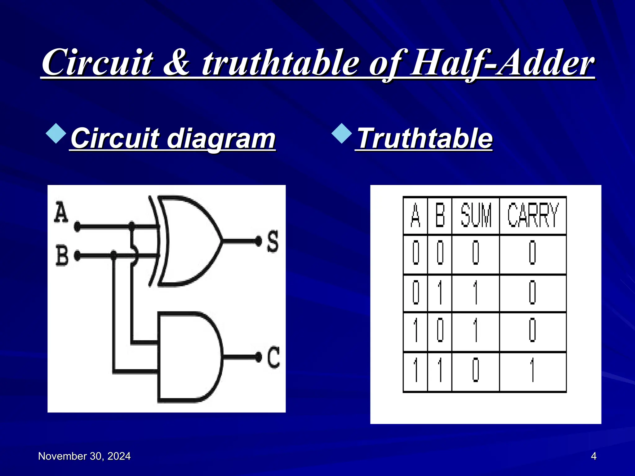
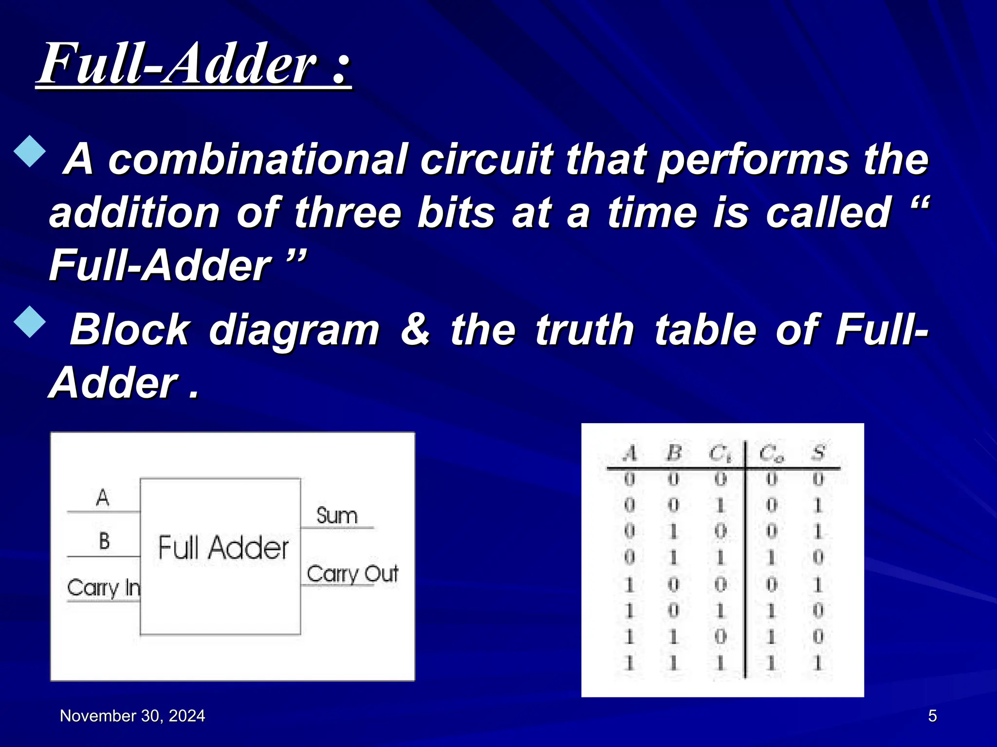
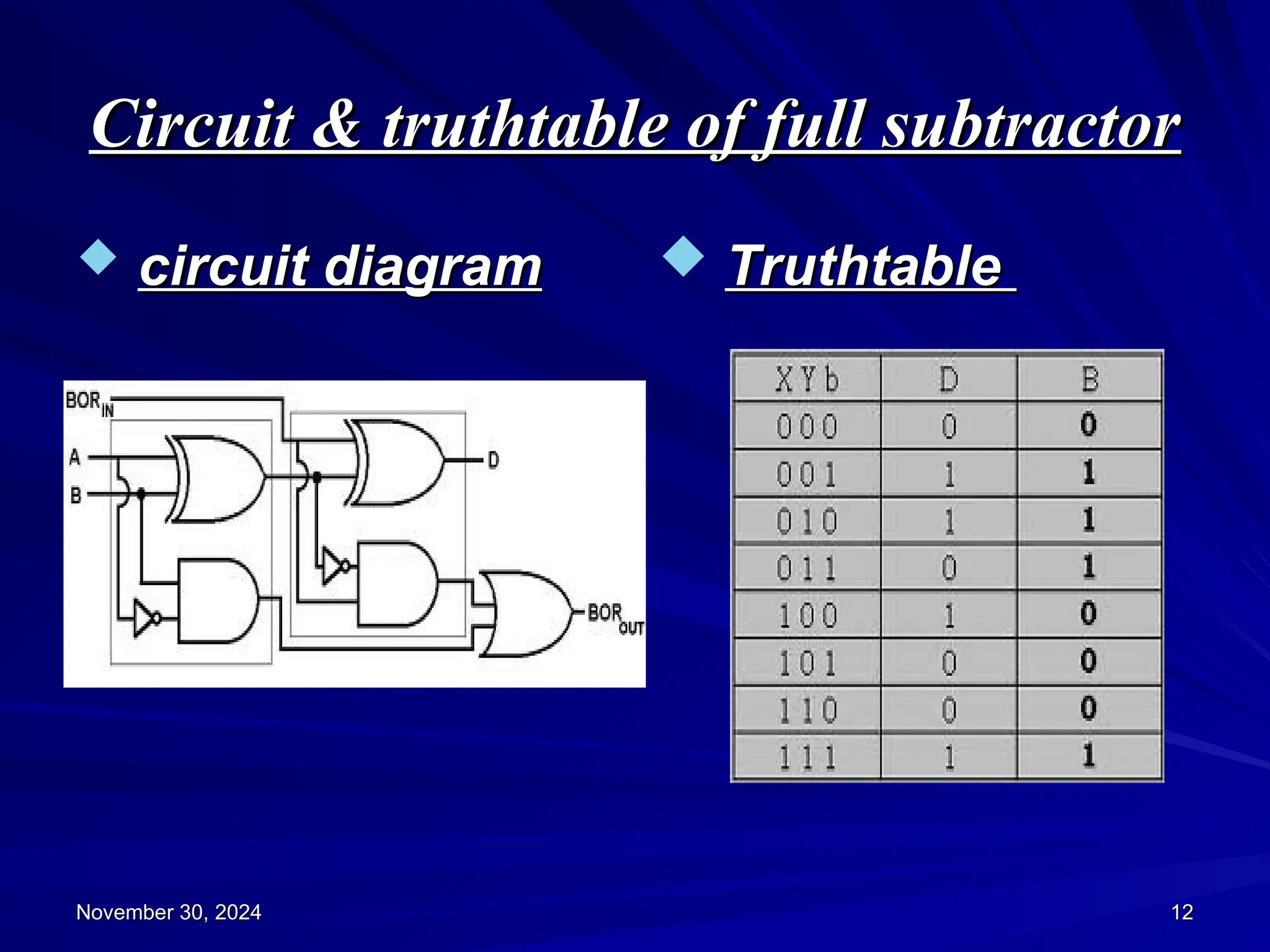
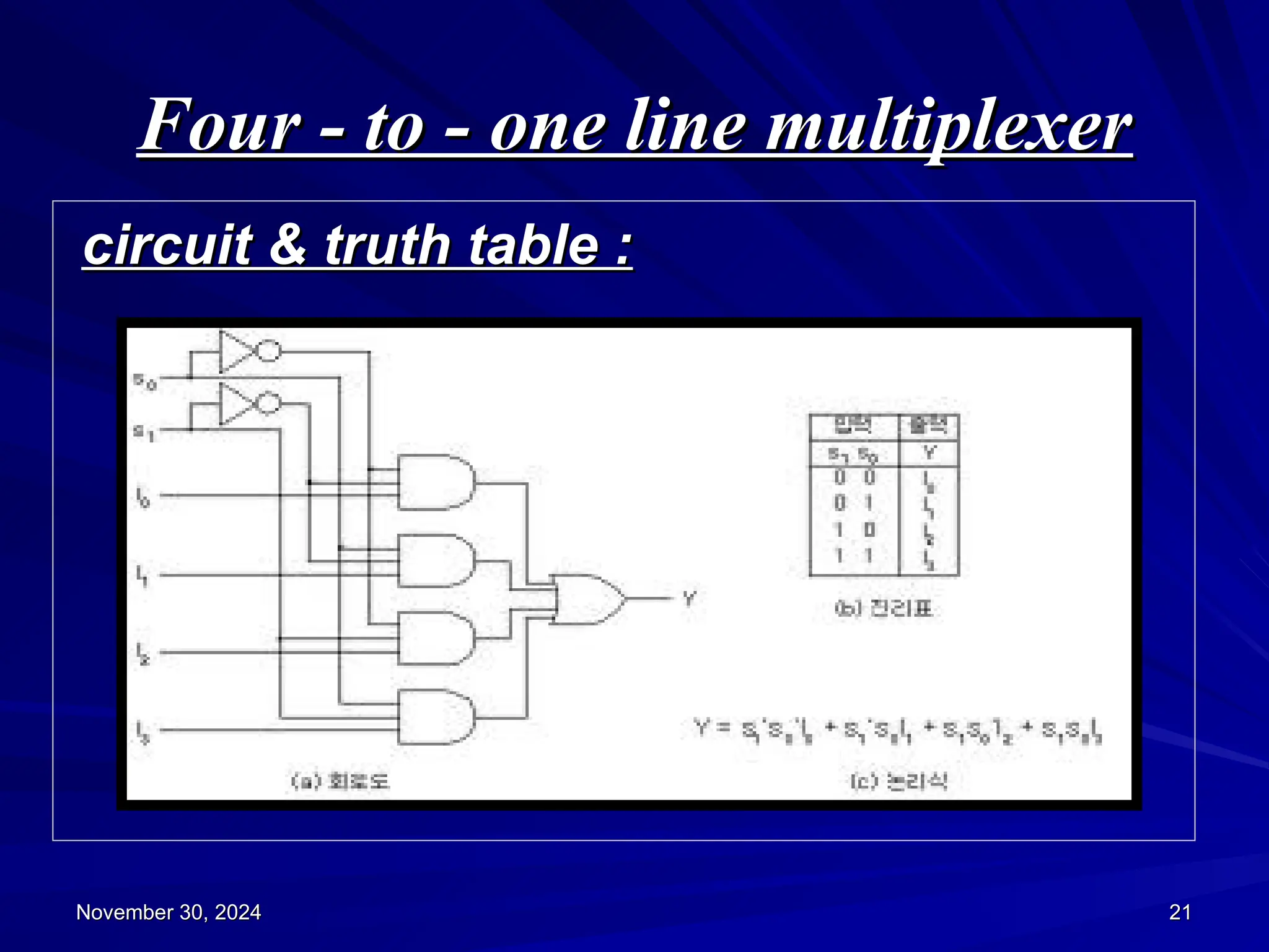
overview
overview
 What is combinational logic circuit ?
What is combinational logic circuit ?
 Examples of combinational logic
Examples of combinational logic
circuits
circuits
 Binary-adder
Binary-adder
 Binary-subtractor
Binary-subtractor
 Binary-multiplier
Binary-multiplier
 Decoders
Decoders
 Multiplexers
Multiplexers
November 30, 2024
November 30, 2024 1
1
Combinational logic circuit
 Combinational circuits consists of
Combinational circuits consists of
logic gates whose outputs depends on
the present inputs .They have no
memory element .
memory element .
 It consists of input variables , logic
It consists of input variables , logic
gates & output variables .
November 30, 2024
November 30, 2024 2
2
Binary-Adder
Binary-Adder
 Half-Adder :
Half-Adder :
 A combinational circuit that performs
A combinational circuit that performs
the addition of two bits at a time is called
“ Full-Adder ‘’ .
“ Full-Adder ‘’ .
 The input variables designate the
The input variables designate the
augend and addend bits ; the output
variables produce the sum & carry .
November 30, 2024
November 30, 2024 3
3
Circuit & truthtable of Half-Adder
Circuit diagram
Circuit diagram Truthtable
Truthtable
November 30, 2024
November 30, 2024 4
4
November 30, 2024
November 30, 2024 5
5
Full-Adder :
Full-Adder :
 A combinational circuit that performs the
A combinational circuit that performs the
addition of three bits at a time is called “
Full-Adder ’’
Full-Adder ’’
 Block diagram & the truth table of Full-
Block diagram & the truth table of Full-
Adder .
Adder .
Circuit diagrams of full-adder
November 30, 2024
November 30, 2024 6
6
Binary-Adder
Binary-Adder
 A Binary-Adder is a digital circuit that
A Binary-Adder is a digital circuit that
produces the arthimatic sum of two
binary numbers at a time .
 It can also construct by cascading no
It can also construct by cascading no
of full-adders we get a N-bit binary-
adder circuit .
adder circuit .
 An N-bit adder requires n full-adders
An N-bit adder requires n full-adders
with each output carry connected to the
input carry to the next full-adder .
November 30, 2024
November 30, 2024 7
7
For adding 4-bit binary numbers we
For adding 4-bit binary numbers we
need four full-adders as shown below :
November 30, 2024
November 30, 2024 8
8
consider two binary numbers
A=1011 & B =0011
A=1011 & B =0011
Binary-subtractor
Binary-subtractor
 Half-subtractor :
Half-subtractor :
 A combinational circuit which performs
A combinational circuit which performs
the subtraction of two bits at a time is
called “ Half-subtractor “ .
 It has two inputs & two outputs . The two
It has two inputs & two outputs . The two
inputs x & y form the minuend &
subtrahend & D is the difference output &
B is the borrow output .
November 30, 2024
November 30, 2024 9
9
Circuit & truthtable of half-
subtractor
subtractor
 circuit diagram
circuit diagram  Truthtable
Truthtable
November 30, 2024
November 30, 2024 10
10
Full subtractor
Full subtractor
 A combinational circuit which
A combinational circuit which
performs the subtraction of three bits
at a time is called “ Full subtractor “ .
 A full subtractor has three inputs x y
A full subtractor has three inputs x y
Bin & two outputs D & Bout .
November 30, 2024
November 30, 2024 11
11
Circuit & truthtable of full subtractor
 circuit diagram
circuit diagram  Truthtable
Truthtable
November 30, 2024
November 30, 2024 12
12
Binary-subtractor
Binary-subtractor
 The subtraction can be done by taking
The subtraction can be done by taking
the 2’s compliment of B and adding it
to A .
to A .
 2’s compliment can be obtained by
2’s compliment can be obtained by
taking the 1’s compliment and adding 1
to least significant bit .
 1’s compliment can be obtained by
1’s compliment can be obtained by
changing 1’s into 0’s & 0’s into 1’s .
November 30, 2024
November 30, 2024 13
13
Four-bit adder-subtractor
November 30, 2024
November 30, 2024 14
14
Continues…..
Continues…..
 In this circuit the mode input m
In this circuit the mode input m
controls the operation . When m=0 , the
circuit is an adder circuit . When m=1,
the
the circuit becomes a subtractor .
circuit becomes a subtractor .
 The c & v are two outputs . C is for
The c & v are two outputs . C is for
carry & v is for overflow . If v=0 after an
addition or subtraction ,then no
overflow occurred and the n-bit result
is correct . If v=1 , then the result of the
operation contains n+1 bits .
November 30, 2024
November 30, 2024 15
15
Binary-multiplier
Binary-multiplier
November 30, 2024
November 30, 2024 16
16
 The multiplication of binary numbers
The multiplication of binary numbers
is performed in the same way as
multiplication of decimal numbers .
 If we take the multiplication of 2-bit
If we take the multiplication of 2-bit
numbers . The multiplicand bits are
B1 & B0 , the multiplier bits are A1 &
A0 and the product is C3,C2,C1,C0 .
2-bit by 2-bit multiplier circuit
November 30, 2024
November 30, 2024 17
17
Decoders
Decoders
 A decoder is a combinational circuit
A decoder is a combinational circuit
that converts binary information from n
input lines to a maximum of 2n unique
output lines .
output lines .
 Generally a decoder is called as n to m
Generally a decoder is called as n to m
line decoder .
line decoder .
 A decoder is used to convert binary
A decoder is used to convert binary
form to any other desired form .
November 30, 2024
November 30, 2024 18
18
Three - to - eight line decoder
 This three - to - eight line decoder is
This three - to - eight line decoder is
used to binary to octal conversions
used to binary to octal conversions .
.
November 30, 2024
November 30, 2024 19
19
Multiplexer
Multiplexer
 multiplexer is a combinational circuit
multiplexer is a combinational circuit
that selects binary information from
one of many input lines and directs it to
a single output line .
 Normally there are 2n input lines and n
Normally there are 2n input lines and n
selection lines whose bit combinations
determines which input is selected .
 A multiplexer is also called ‘ Data
A multiplexer is also called ‘ Data
selector ’
selector ’
November 30, 2024
November 30, 2024 20
20
Four - to - one line multiplexer
circuit & truth table :
November 30, 2024
November 30, 2024 21
21
THANK YOU
THANK YOU
November 30, 2024
November 30, 2024 22
22

ABOUT THE DIGITAL ELECTRONIC TOPIC CIRCUIT DESIGN

  • 1.
    overview overview  What iscombinational logic circuit ? What is combinational logic circuit ?  Examples of combinational logic Examples of combinational logic circuits circuits  Binary-adder Binary-adder  Binary-subtractor Binary-subtractor  Binary-multiplier Binary-multiplier  Decoders Decoders  Multiplexers Multiplexers November 30, 2024 November 30, 2024 1 1
  • 2.
    Combinational logic circuit Combinationallogic circuit  Combinational circuits consists of Combinational circuits consists of logic gates whose outputs depends on logic gates whose outputs depends on the present inputs .They have no the present inputs .They have no memory element . memory element .  It consists of input variables , logic It consists of input variables , logic gates & output variables . gates & output variables . November 30, 2024 November 30, 2024 2 2
  • 3.
    Binary-Adder Binary-Adder  Half-Adder : Half-Adder:  A combinational circuit that performs A combinational circuit that performs the addition of two bits at a time is called the addition of two bits at a time is called “ Full-Adder ‘’ . “ Full-Adder ‘’ .  The input variables designate the The input variables designate the augend and addend bits ; the output augend and addend bits ; the output variables produce the sum & carry . variables produce the sum & carry . November 30, 2024 November 30, 2024 3 3
  • 4.
    Circuit & truthtableof Half-Adder Circuit & truthtable of Half-Adder Circuit diagram Circuit diagram Truthtable Truthtable November 30, 2024 November 30, 2024 4 4
  • 5.
    November 30, 2024 November30, 2024 5 5 Full-Adder : Full-Adder :  A combinational circuit that performs the A combinational circuit that performs the addition of three bits at a time is called “ addition of three bits at a time is called “ Full-Adder ’’ Full-Adder ’’  Block diagram & the truth table of Full- Block diagram & the truth table of Full- Adder . Adder .
  • 6.
    Circuit diagrams offull-adder Circuit diagrams of full-adder November 30, 2024 November 30, 2024 6 6
  • 7.
    Binary-Adder Binary-Adder  A Binary-Adderis a digital circuit that A Binary-Adder is a digital circuit that produces the arthimatic sum of two produces the arthimatic sum of two binary numbers at a time . binary numbers at a time .  It can also construct by cascading no It can also construct by cascading no of full-adders we get a N-bit binary- of full-adders we get a N-bit binary- adder circuit . adder circuit .  An N-bit adder requires n full-adders An N-bit adder requires n full-adders with each output carry connected to the with each output carry connected to the input carry to the next full-adder . input carry to the next full-adder . November 30, 2024 November 30, 2024 7 7
  • 8.
    For adding 4-bitbinary numbers we For adding 4-bit binary numbers we need four full-adders as shown below : need four full-adders as shown below : November 30, 2024 November 30, 2024 8 8 consider two binary numbers consider two binary numbers A=1011 & B =0011 A=1011 & B =0011
  • 9.
    Binary-subtractor Binary-subtractor  Half-subtractor : Half-subtractor:  A combinational circuit which performs A combinational circuit which performs the subtraction of two bits at a time is the subtraction of two bits at a time is called “ Half-subtractor “ . called “ Half-subtractor “ .  It has two inputs & two outputs . The two It has two inputs & two outputs . The two inputs x & y form the minuend & inputs x & y form the minuend & subtrahend & D is the difference output & subtrahend & D is the difference output & B is the borrow output . B is the borrow output . November 30, 2024 November 30, 2024 9 9
  • 10.
    Circuit & truthtableof half- Circuit & truthtable of half- subtractor subtractor  circuit diagram circuit diagram  Truthtable Truthtable November 30, 2024 November 30, 2024 10 10
  • 11.
    Full subtractor Full subtractor A combinational circuit which A combinational circuit which performs the subtraction of three bits performs the subtraction of three bits at a time is called “ Full subtractor “ . at a time is called “ Full subtractor “ .  A full subtractor has three inputs x y A full subtractor has three inputs x y Bin & two outputs D & Bout . Bin & two outputs D & Bout . November 30, 2024 November 30, 2024 11 11
  • 12.
    Circuit & truthtableof full subtractor Circuit & truthtable of full subtractor  circuit diagram circuit diagram  Truthtable Truthtable November 30, 2024 November 30, 2024 12 12
  • 13.
    Binary-subtractor Binary-subtractor  The subtractioncan be done by taking The subtraction can be done by taking the 2’s compliment of B and adding it the 2’s compliment of B and adding it to A . to A .  2’s compliment can be obtained by 2’s compliment can be obtained by taking the 1’s compliment and adding 1 taking the 1’s compliment and adding 1 to least significant bit . to least significant bit .  1’s compliment can be obtained by 1’s compliment can be obtained by changing 1’s into 0’s & 0’s into 1’s . changing 1’s into 0’s & 0’s into 1’s . November 30, 2024 November 30, 2024 13 13
  • 14.
  • 15.
    Continues….. Continues…..  In thiscircuit the mode input m In this circuit the mode input m controls the operation . When m=0 , the controls the operation . When m=0 , the circuit is an adder circuit . When m=1, circuit is an adder circuit . When m=1, the the circuit becomes a subtractor . circuit becomes a subtractor .  The c & v are two outputs . C is for The c & v are two outputs . C is for carry & v is for overflow . If v=0 after an carry & v is for overflow . If v=0 after an addition or subtraction ,then no addition or subtraction ,then no overflow occurred and the n-bit result overflow occurred and the n-bit result is correct . If v=1 , then the result of the is correct . If v=1 , then the result of the operation contains n+1 bits . operation contains n+1 bits . November 30, 2024 November 30, 2024 15 15
  • 16.
    Binary-multiplier Binary-multiplier November 30, 2024 November30, 2024 16 16  The multiplication of binary numbers The multiplication of binary numbers is performed in the same way as is performed in the same way as multiplication of decimal numbers . multiplication of decimal numbers .  If we take the multiplication of 2-bit If we take the multiplication of 2-bit numbers . The multiplicand bits are numbers . The multiplicand bits are B1 & B0 , the multiplier bits are A1 & B1 & B0 , the multiplier bits are A1 & A0 and the product is C3,C2,C1,C0 . A0 and the product is C3,C2,C1,C0 .
  • 17.
    2-bit by 2-bitmultiplier circuit 2-bit by 2-bit multiplier circuit November 30, 2024 November 30, 2024 17 17
  • 18.
    Decoders Decoders  A decoderis a combinational circuit A decoder is a combinational circuit that converts binary information from n that converts binary information from n input lines to a maximum of 2n unique input lines to a maximum of 2n unique output lines . output lines .  Generally a decoder is called as n to m Generally a decoder is called as n to m line decoder . line decoder .  A decoder is used to convert binary A decoder is used to convert binary form to any other desired form . form to any other desired form . November 30, 2024 November 30, 2024 18 18
  • 19.
    Three - to- eight line decoder Three - to - eight line decoder  This three - to - eight line decoder is This three - to - eight line decoder is used to binary to octal conversions used to binary to octal conversions . . November 30, 2024 November 30, 2024 19 19
  • 20.
    Multiplexer Multiplexer  multiplexer isa combinational circuit multiplexer is a combinational circuit that selects binary information from that selects binary information from one of many input lines and directs it to one of many input lines and directs it to a single output line . a single output line .  Normally there are 2n input lines and n Normally there are 2n input lines and n selection lines whose bit combinations selection lines whose bit combinations determines which input is selected . determines which input is selected .  A multiplexer is also called ‘ Data A multiplexer is also called ‘ Data selector ’ selector ’ November 30, 2024 November 30, 2024 20 20
  • 21.
    Four - to- one line multiplexer Four - to - one line multiplexer circuit & truth table : circuit & truth table : November 30, 2024 November 30, 2024 21 21
  • 22.
    THANK YOU THANK YOU November30, 2024 November 30, 2024 22 22