Downloaded 1,073 times


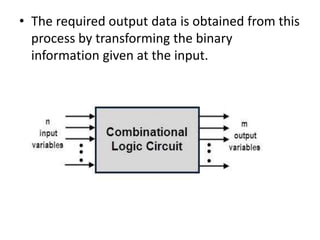
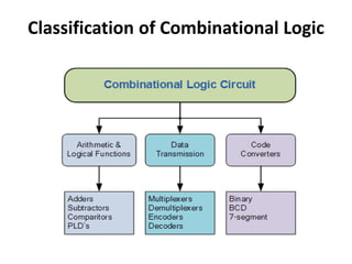
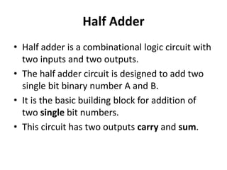
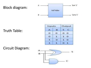
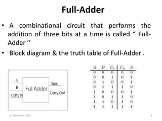
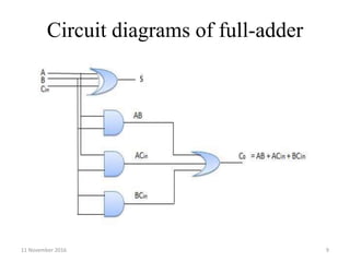
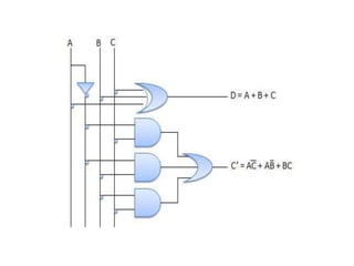

A combinational circuit is a logic circuit whose output is solely determined by the present input. It has no internal memory and its output depends only on the current inputs. A half adder is a basic combinational circuit that adds two single bits and produces a sum and carry output. A full adder adds three bits and produces a sum and carry like the half adder. Other combinational circuits discussed include half and full subtractors, decoders, encoders, and priority encoders.


![Getting Started with Apache Spark: Big Data Made Simple [Free Meetup]](https://cdn.slidesharecdn.com/ss_thumbnails/apachesparkgettingstarted-260203175547-8361bcc3-thumbnail.jpg?width=640&height=640&fit=bounds)