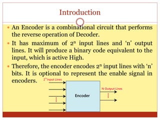
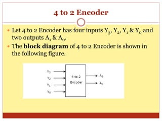
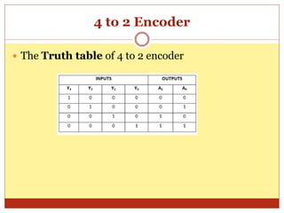
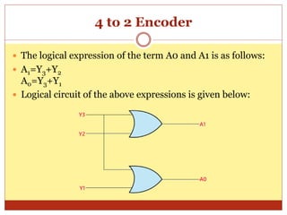
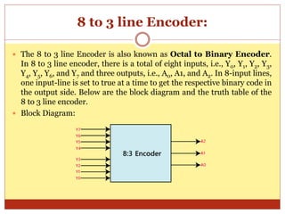
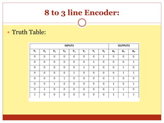
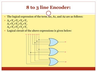
P R O F . N E E R A J B H A R G A V A
M R S . P O O J A D I X I T
D E P A R T M E N T O F C O M P U T E R S C I E N C E ,
S C H O O L O F E N G I N E E R I N G & S Y S T E M
S C I E N C E S
M D S U N I V E R S I T Y A J M E R , R A J A S T H A N
Encoder
Introduction
 An Encoder is a combinational circuit that performs
the reverse operation of Decoder.
 It has maximum of 2n input lines and ‘n’ output
lines. It will produce a binary code equivalent to the
input, which is active High.
 Therefore, the encoder encodes 2n input lines with ‘n’
bits. It is optional to represent the enable signal in
encoders.
4 to 2 Encoder
 Let 4 to 2 Encoder has four inputs Y3, Y2, Y1 & Y0 and
two outputs A1 & A0.
 The block diagram of 4 to 2 Encoder is shown in
the following figure.
4 to 2 Encoder
 The Truth table of 4 to 2 encoder
4 to 2 Encoder
 The logical expression of the term A0 and A1 is as follows:
 A1=Y3+Y2
A0=Y3+Y1
 Logical circuit of the above expressions is given below:
8 to 3 line Encoder:
 The 8 to 3 line Encoder is also known as Octal to Binary Encoder.
In 8 to 3 line encoder, there is a total of eight inputs, i.e., Y0, Y1, Y2, Y3,
Y4, Y5, Y6, and Y7 and three outputs, i.e., A0, A1, and A2. In 8-input lines,
one input-line is set to true at a time to get the respective binary code in
the output side. Below are the block diagram and the truth table of the
8 to 3 line encoder.
 Block Diagram:
8 to 3 line Encoder:
 Truth Table:
8 to 3 line Encoder:
 The logical expression of the term A0, A1, and A2 are as follows:
 A2=Y4+Y5+Y6+Y7
A1=Y2+Y3+Y6+Y7
A0=Y7+Y5+Y3+Y1
 Logical circuit of the above expressions is given below:
Uses of Encoders:
 These systems are very easy to use in all digital
systems.
 Encoders are used to convert a decimal number into
the binary number. The objective is to perform a
binary operation such as addition, subtraction,
multiplication, etc.

Encoder.pptx

  • 1.
    P R OF . N E E R A J B H A R G A V A M R S . P O O J A D I X I T D E P A R T M E N T O F C O M P U T E R S C I E N C E , S C H O O L O F E N G I N E E R I N G & S Y S T E M S C I E N C E S M D S U N I V E R S I T Y A J M E R , R A J A S T H A N Encoder
  • 2.
    Introduction  An Encoderis a combinational circuit that performs the reverse operation of Decoder.  It has maximum of 2n input lines and ‘n’ output lines. It will produce a binary code equivalent to the input, which is active High.  Therefore, the encoder encodes 2n input lines with ‘n’ bits. It is optional to represent the enable signal in encoders.
  • 3.
    4 to 2Encoder  Let 4 to 2 Encoder has four inputs Y3, Y2, Y1 & Y0 and two outputs A1 & A0.  The block diagram of 4 to 2 Encoder is shown in the following figure.
  • 4.
    4 to 2Encoder  The Truth table of 4 to 2 encoder
  • 5.
    4 to 2Encoder  The logical expression of the term A0 and A1 is as follows:  A1=Y3+Y2 A0=Y3+Y1  Logical circuit of the above expressions is given below:
  • 6.
    8 to 3line Encoder:  The 8 to 3 line Encoder is also known as Octal to Binary Encoder. In 8 to 3 line encoder, there is a total of eight inputs, i.e., Y0, Y1, Y2, Y3, Y4, Y5, Y6, and Y7 and three outputs, i.e., A0, A1, and A2. In 8-input lines, one input-line is set to true at a time to get the respective binary code in the output side. Below are the block diagram and the truth table of the 8 to 3 line encoder.  Block Diagram:
  • 7.
    8 to 3line Encoder:  Truth Table:
  • 8.
    8 to 3line Encoder:  The logical expression of the term A0, A1, and A2 are as follows:  A2=Y4+Y5+Y6+Y7 A1=Y2+Y3+Y6+Y7 A0=Y7+Y5+Y3+Y1  Logical circuit of the above expressions is given below:
  • 9.
    Uses of Encoders: These systems are very easy to use in all digital systems.  Encoders are used to convert a decimal number into the binary number. The objective is to perform a binary operation such as addition, subtraction, multiplication, etc.