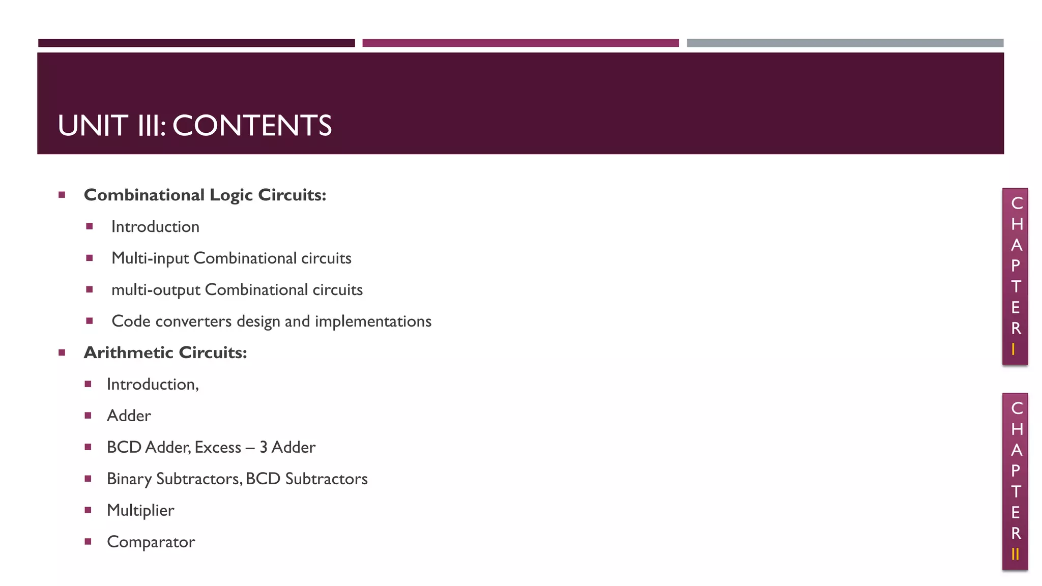
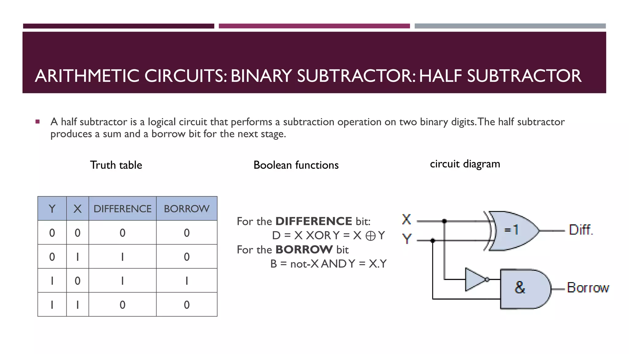
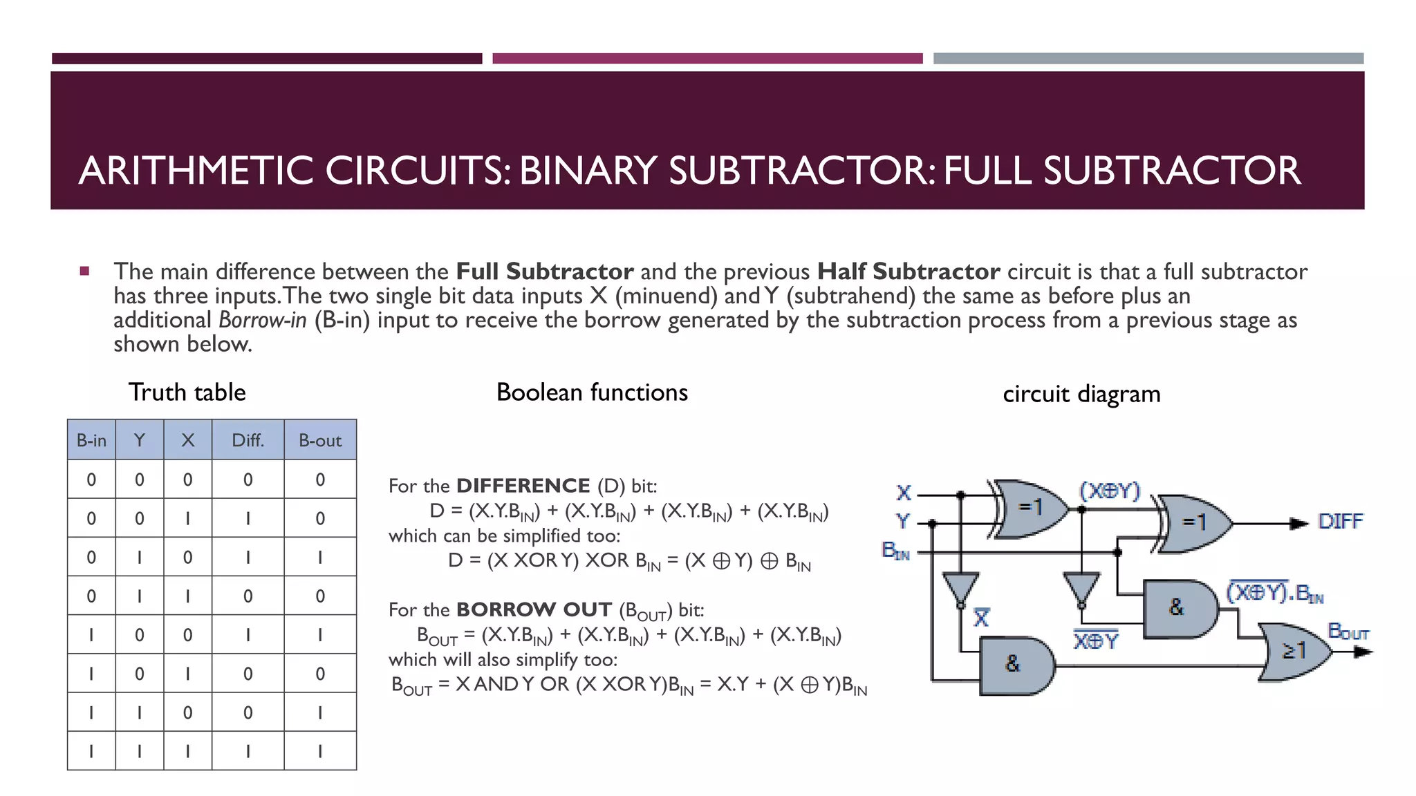
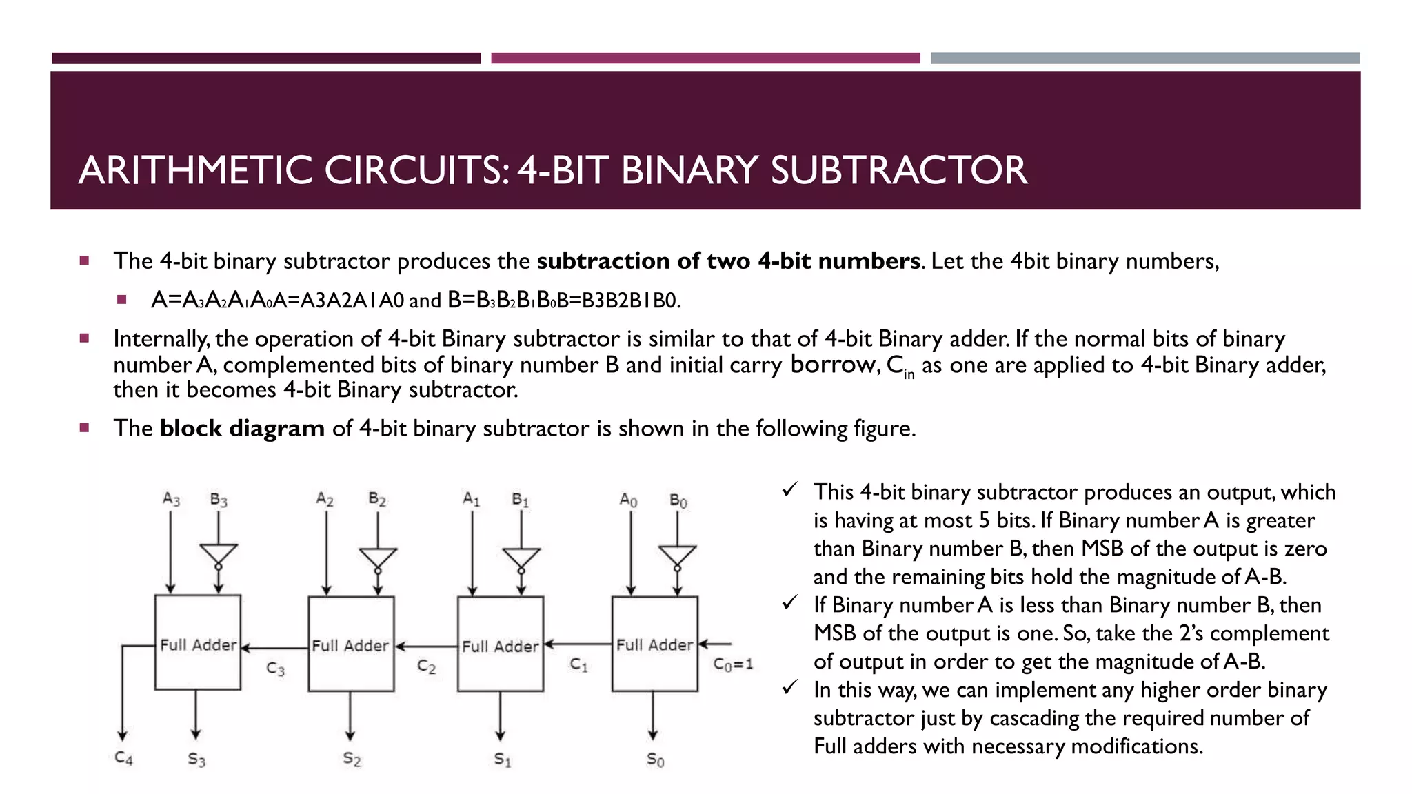
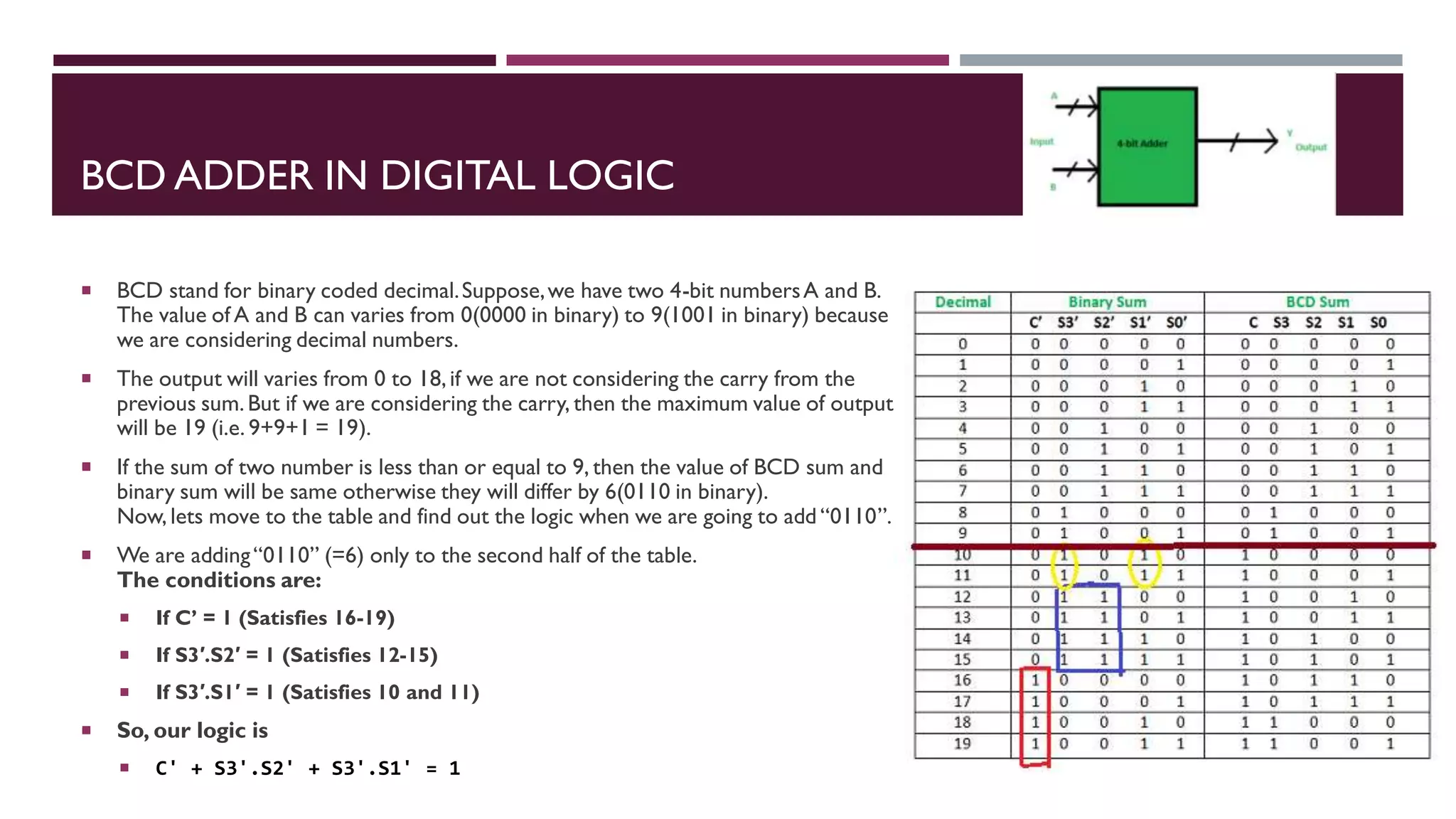
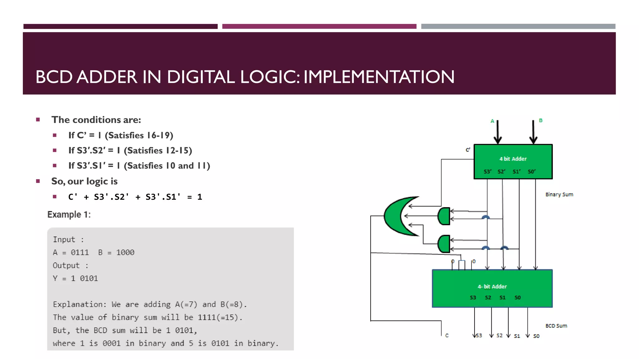
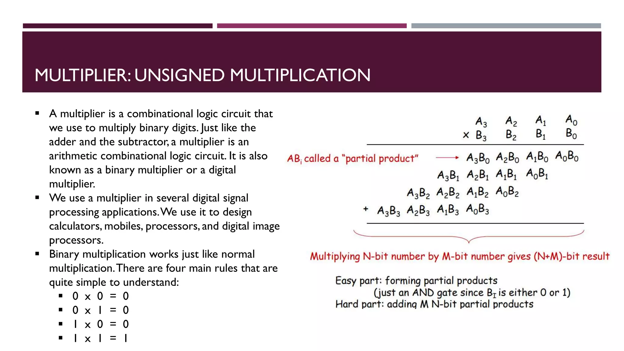
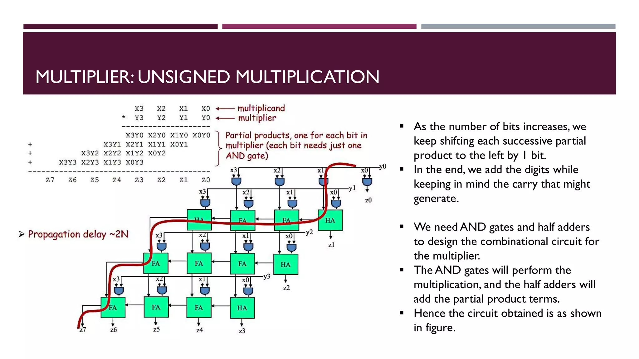
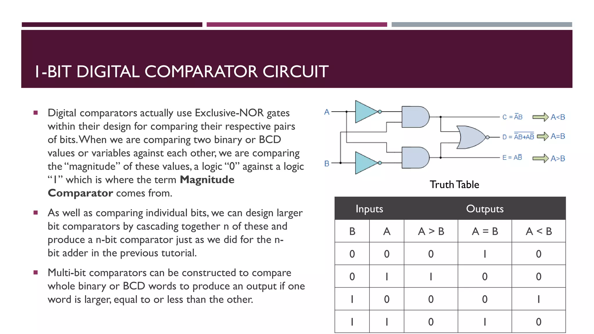
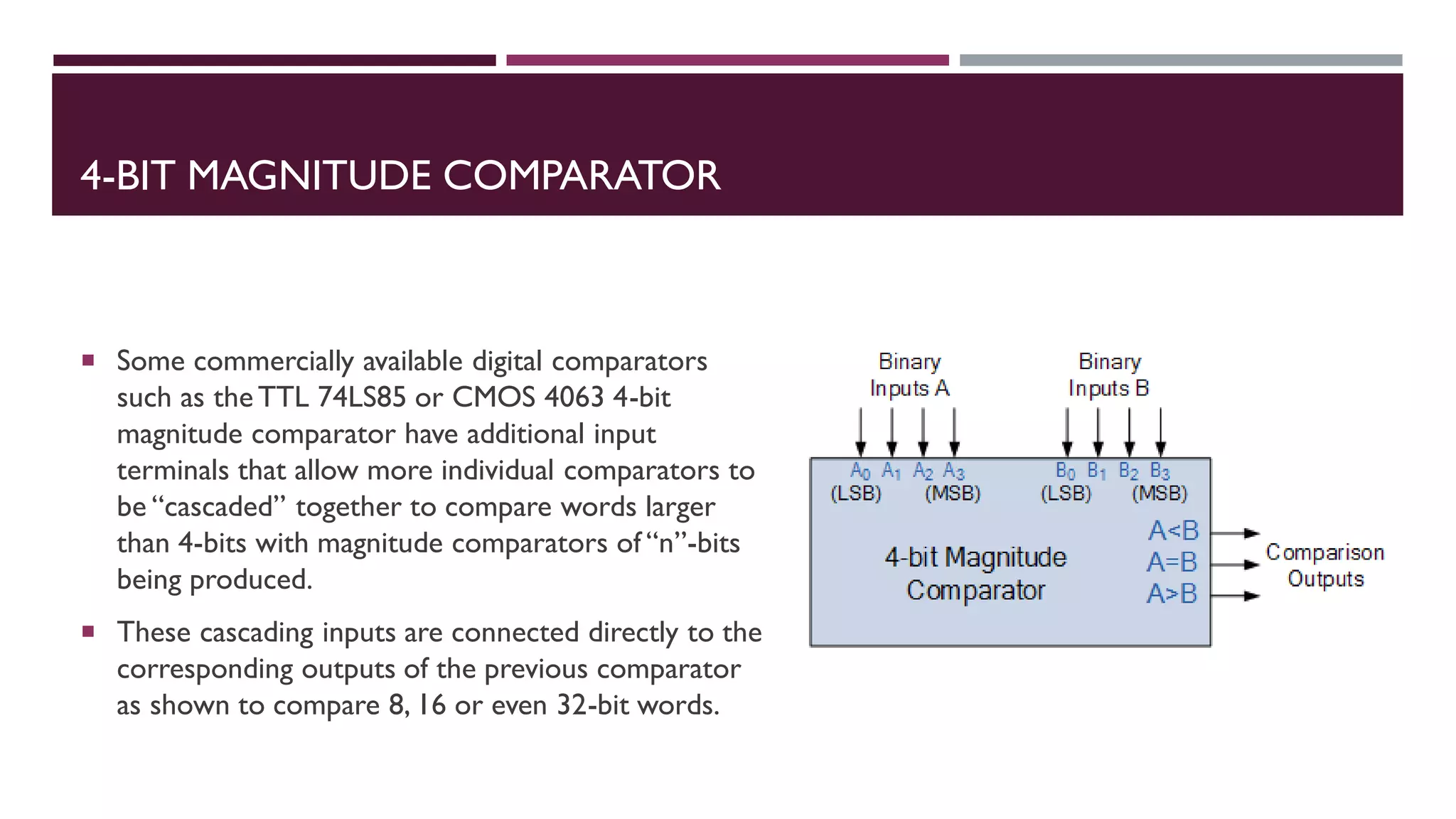
COMBINATIONAL
LOGIC CIRCUITS
&
ARITHMETIC
CIRCUITS
UNIT III
DIGITAL
ELECTRONICS
PROF.ARTI GAVAS-PARAB
ANNA LEELA COLLEGE OF COMMERCE AND ECONOMICS,SHOBHA
JAYARAM SHETTY COLLEGE FOR BMS
CHAPTER II
UNIT III: CONTENTS
 Combinational Logic Circuits:
 Introduction
 Multi-input Combinational circuits
 multi-output Combinational circuits
 Code converters design and implementations
 Arithmetic Circuits:
 Introduction,
 Adder
 BCD Adder, Excess – 3 Adder
 Binary Subtractors,BCD Subtractors
 Multiplier
 Comparator
C
H
A
P
T
E
R
I
C
H
A
P
T
E
R
II
ARITHMETIC CIRCUITS
 Originally, the basic arithmetic circuits were designed using discrete components,but this method has long been
superseded by the introduction of MSI circuits.
 Multi-bit adders, arithmetic logic units and other circuits are now readily available as medium scale
integrated circuits.
 Basic arithmetic circuits are Binary adder and Binary subtractor.
 These circuits can be operated with binary values 0 and 1.
 Adder,
 BCD Adder,
 Excess – 3 Adder,
 Binary Subtractors,
 BCD Subtractor,
 Multiplier,
 Comparator
ARITHMETIC CIRCUITS: BINARY ADDER:HALF ADDER
 The most basic arithmetic operation is addition.The circuit, which performs the addition of two binary numbers
is known as Binary adder. First, let us implement an adder, which performs the addition of two bits.
 Half adder is a combinational circuit, which performs the addition of two binary numbers A and B are of single
bit. It produces two outputs sum, S & carry, C.
Inputs Outputs
A B C S
0 0 0 0
0 1 0 1
1 0 0 1
1 1 1 0
S=A⊕B
C=AB
Truth table Boolean functions circuit diagram
ARITHMETIC CIRCUITS: BINARY ADDER:FULL ADDER
 Full adder is a combinational circuit, which performs the addition of three bits A, B and Cin.Where,A & B are
the two parallel significant bits and Cin is the carry bit, which is generated from previous stage.This Full adder also
produces two outputs sum, S & carry, Cout, which are similar to Half adder.
S=A⊕B⊕Cin
cout=AB+(A⊕B)Cin
Truth table
Boolean functions
circuit diagramInputs Outputs
A B Cin Cout S
0 0 0 0 0
0 0 1 0 1
0 1 0 0 1
0 1 1 1 0
1 0 0 0 1
1 0 1 1 0
1 1 0 1 0
1 1 1 1 1
ARITHMETIC CIRCUITS: BINARY ADDER:4-BIT BINARY ADDER
 The 4-bit binary adder performs the addition of two 4-bit numbers. Let the 4-bit binary numbers,
A=A3A2A1A0 and B=B3B2B1B0.
 Use four Full adders for uniformity. Since, initial carry Cin is zero, the Full adder which is used for adding the least
significant bits becomes Half adder.
 The block diagram of 4-bit binary adder is shown in the following figure.
 Here, the 4 Full adders are cascaded. Each Full adder
is getting the respective bits of two parallel inputs A
& B. The carry output of one Full adder will be the
carry input of subsequent higher order Full adder.
 In this way, we can implement any higher order
binary adder just by cascading the required number
of Full adders.
 This binary adder is also called as ripple carry
binary adder because the carry propagates ripples
from one stage to the next stage.
ARITHMETIC CIRCUITS: BINARY SUBTRACTOR:HALF SUBTRACTOR
 A half subtractor is a logical circuit that performs a subtraction operation on two binary digits.The half subtractor
produces a sum and a borrow bit for the next stage.
Y X DIFFERENCE BORROW
0 0 0 0
0 1 1 0
1 0 1 1
1 1 0 0
For the DIFFERENCE bit:
D = X XORY = X ⊕Y
For the BORROW bit
B = not-X ANDY = X.Y
Truth table Boolean functions circuit diagram
ARITHMETIC CIRCUITS: BINARY SUBTRACTOR:FULL SUBTRACTOR
 The main difference between the Full Subtractor and the previous Half Subtractor circuit is that a full subtractor
has three inputs.The two single bit data inputs X (minuend) andY (subtrahend) the same as before plus an
additional Borrow-in (B-in) input to receive the borrow generated by the subtraction process from a previous stage as
shown below.
B-in Y X Diff. B-out
0 0 0 0 0
0 0 1 1 0
0 1 0 1 1
0 1 1 0 0
1 0 0 1 1
1 0 1 0 0
1 1 0 0 1
1 1 1 1 1
For the DIFFERENCE (D) bit:
D = (X.Y.BIN) + (X.Y.BIN) + (X.Y.BIN) + (X.Y.BIN)
which can be simplified too:
D = (X XORY) XOR BIN = (X ⊕Y) ⊕ BIN
For the BORROW OUT (BOUT) bit:
BOUT = (X.Y.BIN) + (X.Y.BIN) + (X.Y.BIN) + (X.Y.BIN)
which will also simplify too:
BOUT = X ANDY OR (X XORY)BIN = X.Y + (X ⊕Y)BIN
Truth table Boolean functions circuit diagram
ARITHMETIC CIRCUITS: 4-BIT BINARY SUBTRACTOR
 The 4-bit binary subtractor produces the subtraction of two 4-bit numbers. Let the 4bit binary numbers,
 A=A3A2A1A0A=A3A2A1A0 and B=B3B2B1B0B=B3B2B1B0.
 Internally, the operation of 4-bit Binary subtractor is similar to that of 4-bit Binary adder. If the normal bits of binary
number A, complemented bits of binary number B and initial carry borrow, Cin as one are applied to 4-bit Binary adder,
then it becomes 4-bit Binary subtractor.
 The block diagram of 4-bit binary subtractor is shown in the following figure.
 This 4-bit binary subtractor produces an output, which
is having at most 5 bits. If Binary numberA is greater
than Binary number B, then MSB of the output is zero
and the remaining bits hold the magnitude of A-B.
 If Binary numberA is less than Binary number B, then
MSB of the output is one. So, take the 2’s complement
of output in order to get the magnitude of A-B.
 In this way, we can implement any higher order binary
subtractor just by cascading the required number of
Full adders with necessary modifications.
BCD ADDER IN DIGITAL LOGIC
 BCD stand for binary coded decimal.Suppose,we have two 4-bit numbersA and B.
The value of A and B can varies from 0(0000 in binary) to 9(1001 in binary) because
we are considering decimal numbers.
 The output will varies from 0 to 18,if we are not considering the carry from the
previous sum.But if we are considering the carry, then the maximum value of output
will be 19 (i.e. 9+9+1 = 19).
 If the sum of two number is less than or equal to 9, then the value of BCD sum and
binary sum will be same otherwise they will differ by 6(0110 in binary).
Now, lets move to the table and find out the logic when we are going to add “0110”.
 We are adding“0110” (=6) only to the second half of the table.
The conditions are:
 If C’ = 1 (Satisfies 16-19)
 If S3′.S2′ = 1 (Satisfies 12-15)
 If S3′.S1′ = 1 (Satisfies 10 and 11)
 So, our logic is
 C' + S3'.S2' + S3'.S1' = 1
BCD ADDER IN DIGITAL LOGIC: IMPLEMENTATION
 The conditions are:
 If C’ = 1 (Satisfies 16-19)
 If S3′.S2′ = 1 (Satisfies 12-15)
 If S3′.S1′ = 1 (Satisfies 10 and 11)
 So, our logic is
 C' + S3'.S2' + S3'.S1' = 1
ARITHMETIC CIRCUITS: EXCESS – 3 ADDER
MULTIPLIER: UNSIGNED MULTIPLICATION
 A multiplier is a combinational logic circuit that
we use to multiply binary digits. Just like the
adder and the subtractor, a multiplier is an
arithmetic combinational logic circuit. It is also
known as a binary multiplier or a digital
multiplier.
 We use a multiplier in several digital signal
processing applications.We use it to design
calculators, mobiles, processors, and digital image
processors.
 Binary multiplication works just like normal
multiplication.There are four main rules that are
quite simple to understand:
 0 x 0 = 0
 0 x 1 = 0
 1 x 0 = 0
 1 x 1 = 1
MULTIPLIER: UNSIGNED MULTIPLICATION
 As the number of bits increases, we
keep shifting each successive partial
product to the left by 1 bit.
 In the end, we add the digits while
keeping in mind the carry that might
generate.
 We need AND gates and half adders
to design the combinational circuit for
the multiplier.
 The AND gates will perform the
multiplication, and the half adders will
add the partial product terms.
 Hence the circuit obtained is as shown
in figure.
DIGITAL COMPARATOR
 The Digital Comparator is another very useful combinational logic circuit used to compare the value of two binary
digits
 Digital or Binary Comparators are made up from standard AND, NOR and NOT gates that compare the digital signals
present at their input terminals and produce an output depending upon the condition of those inputs.
 For example, along with being able to add and subtract binary numbers we need to be able to compare them and
determine whether the value of input A is greater than,smaller than or equal to the value at input B etc.The digital
comparator accomplishes this using several logic gates that operate on the principles of Boolean Algebra.There are two
main types of Digital Comparator available and these are.
 1. Identity Comparator – an Identity Comparator is a digital comparator with only one output terminal for when A = B,
either A = B = 1 (HIGH) or A = B = 0 (LOW)
 2. Magnitude Comparator – a Magnitude Comparator is a digital comparator which has three output terminals,one each
for equality,A = B greater than,A > B and less than A < B
 The purpose of a Digital Comparator is to compare a set of variables or unknown numbers, for example A (A1,A2,
A3, ….An, etc) against that of a constant or unknown value such as B (B1, B2, B3, …. Bn, etc) and produce an output
condition or flag depending upon the result of the comparison.
1-BIT DIGITAL COMPARATOR CIRCUIT
 Digital comparators actually use Exclusive-NOR gates
within their design for comparing their respective pairs
of bits.When we are comparing two binary or BCD
values or variables against each other, we are comparing
the “magnitude” of these values, a logic “0” against a logic
“1” which is where the term Magnitude
Comparator comes from.
 As well as comparing individual bits, we can design larger
bit comparators by cascading together n of these and
produce a n-bit comparator just as we did for the n-
bit adder in the previous tutorial.
 Multi-bit comparators can be constructed to compare
whole binary or BCD words to produce an output if one
word is larger, equal to or less than the other.
Inputs Outputs
B A A > B A = B A < B
0 0 0 1 0
0 1 1 0 0
1 0 0 0 1
1 1 0 1 0
TruthTable
4-BIT MAGNITUDE COMPARATOR
 Some commercially available digital comparators
such as theTTL 74LS85 or CMOS 4063 4-bit
magnitude comparator have additional input
terminals that allow more individual comparators to
be “cascaded” together to compare words larger
than 4-bits with magnitude comparators of “n”-bits
being produced.
 These cascading inputs are connected directly to the
corresponding outputs of the previous comparator
as shown to compare 8, 16 or even 32-bit words.
THANKYOU!

FYBSC IT Digital Electronics Unit III Chapter II Arithmetic Circuits

  • 1.
    COMBINATIONAL LOGIC CIRCUITS & ARITHMETIC CIRCUITS UNIT III DIGITAL ELECTRONICS PROF.ARTIGAVAS-PARAB ANNA LEELA COLLEGE OF COMMERCE AND ECONOMICS,SHOBHA JAYARAM SHETTY COLLEGE FOR BMS CHAPTER II
  • 2.
    UNIT III: CONTENTS Combinational Logic Circuits:  Introduction  Multi-input Combinational circuits  multi-output Combinational circuits  Code converters design and implementations  Arithmetic Circuits:  Introduction,  Adder  BCD Adder, Excess – 3 Adder  Binary Subtractors,BCD Subtractors  Multiplier  Comparator C H A P T E R I C H A P T E R II
  • 3.
    ARITHMETIC CIRCUITS  Originally,the basic arithmetic circuits were designed using discrete components,but this method has long been superseded by the introduction of MSI circuits.  Multi-bit adders, arithmetic logic units and other circuits are now readily available as medium scale integrated circuits.  Basic arithmetic circuits are Binary adder and Binary subtractor.  These circuits can be operated with binary values 0 and 1.  Adder,  BCD Adder,  Excess – 3 Adder,  Binary Subtractors,  BCD Subtractor,  Multiplier,  Comparator
  • 4.
    ARITHMETIC CIRCUITS: BINARYADDER:HALF ADDER  The most basic arithmetic operation is addition.The circuit, which performs the addition of two binary numbers is known as Binary adder. First, let us implement an adder, which performs the addition of two bits.  Half adder is a combinational circuit, which performs the addition of two binary numbers A and B are of single bit. It produces two outputs sum, S & carry, C. Inputs Outputs A B C S 0 0 0 0 0 1 0 1 1 0 0 1 1 1 1 0 S=A⊕B C=AB Truth table Boolean functions circuit diagram
  • 5.
    ARITHMETIC CIRCUITS: BINARYADDER:FULL ADDER  Full adder is a combinational circuit, which performs the addition of three bits A, B and Cin.Where,A & B are the two parallel significant bits and Cin is the carry bit, which is generated from previous stage.This Full adder also produces two outputs sum, S & carry, Cout, which are similar to Half adder. S=A⊕B⊕Cin cout=AB+(A⊕B)Cin Truth table Boolean functions circuit diagramInputs Outputs A B Cin Cout S 0 0 0 0 0 0 0 1 0 1 0 1 0 0 1 0 1 1 1 0 1 0 0 0 1 1 0 1 1 0 1 1 0 1 0 1 1 1 1 1
  • 6.
    ARITHMETIC CIRCUITS: BINARYADDER:4-BIT BINARY ADDER  The 4-bit binary adder performs the addition of two 4-bit numbers. Let the 4-bit binary numbers, A=A3A2A1A0 and B=B3B2B1B0.  Use four Full adders for uniformity. Since, initial carry Cin is zero, the Full adder which is used for adding the least significant bits becomes Half adder.  The block diagram of 4-bit binary adder is shown in the following figure.  Here, the 4 Full adders are cascaded. Each Full adder is getting the respective bits of two parallel inputs A & B. The carry output of one Full adder will be the carry input of subsequent higher order Full adder.  In this way, we can implement any higher order binary adder just by cascading the required number of Full adders.  This binary adder is also called as ripple carry binary adder because the carry propagates ripples from one stage to the next stage.
  • 7.
    ARITHMETIC CIRCUITS: BINARYSUBTRACTOR:HALF SUBTRACTOR  A half subtractor is a logical circuit that performs a subtraction operation on two binary digits.The half subtractor produces a sum and a borrow bit for the next stage. Y X DIFFERENCE BORROW 0 0 0 0 0 1 1 0 1 0 1 1 1 1 0 0 For the DIFFERENCE bit: D = X XORY = X ⊕Y For the BORROW bit B = not-X ANDY = X.Y Truth table Boolean functions circuit diagram
  • 8.
    ARITHMETIC CIRCUITS: BINARYSUBTRACTOR:FULL SUBTRACTOR  The main difference between the Full Subtractor and the previous Half Subtractor circuit is that a full subtractor has three inputs.The two single bit data inputs X (minuend) andY (subtrahend) the same as before plus an additional Borrow-in (B-in) input to receive the borrow generated by the subtraction process from a previous stage as shown below. B-in Y X Diff. B-out 0 0 0 0 0 0 0 1 1 0 0 1 0 1 1 0 1 1 0 0 1 0 0 1 1 1 0 1 0 0 1 1 0 0 1 1 1 1 1 1 For the DIFFERENCE (D) bit: D = (X.Y.BIN) + (X.Y.BIN) + (X.Y.BIN) + (X.Y.BIN) which can be simplified too: D = (X XORY) XOR BIN = (X ⊕Y) ⊕ BIN For the BORROW OUT (BOUT) bit: BOUT = (X.Y.BIN) + (X.Y.BIN) + (X.Y.BIN) + (X.Y.BIN) which will also simplify too: BOUT = X ANDY OR (X XORY)BIN = X.Y + (X ⊕Y)BIN Truth table Boolean functions circuit diagram
  • 9.
    ARITHMETIC CIRCUITS: 4-BITBINARY SUBTRACTOR  The 4-bit binary subtractor produces the subtraction of two 4-bit numbers. Let the 4bit binary numbers,  A=A3A2A1A0A=A3A2A1A0 and B=B3B2B1B0B=B3B2B1B0.  Internally, the operation of 4-bit Binary subtractor is similar to that of 4-bit Binary adder. If the normal bits of binary number A, complemented bits of binary number B and initial carry borrow, Cin as one are applied to 4-bit Binary adder, then it becomes 4-bit Binary subtractor.  The block diagram of 4-bit binary subtractor is shown in the following figure.  This 4-bit binary subtractor produces an output, which is having at most 5 bits. If Binary numberA is greater than Binary number B, then MSB of the output is zero and the remaining bits hold the magnitude of A-B.  If Binary numberA is less than Binary number B, then MSB of the output is one. So, take the 2’s complement of output in order to get the magnitude of A-B.  In this way, we can implement any higher order binary subtractor just by cascading the required number of Full adders with necessary modifications.
  • 10.
    BCD ADDER INDIGITAL LOGIC  BCD stand for binary coded decimal.Suppose,we have two 4-bit numbersA and B. The value of A and B can varies from 0(0000 in binary) to 9(1001 in binary) because we are considering decimal numbers.  The output will varies from 0 to 18,if we are not considering the carry from the previous sum.But if we are considering the carry, then the maximum value of output will be 19 (i.e. 9+9+1 = 19).  If the sum of two number is less than or equal to 9, then the value of BCD sum and binary sum will be same otherwise they will differ by 6(0110 in binary). Now, lets move to the table and find out the logic when we are going to add “0110”.  We are adding“0110” (=6) only to the second half of the table. The conditions are:  If C’ = 1 (Satisfies 16-19)  If S3′.S2′ = 1 (Satisfies 12-15)  If S3′.S1′ = 1 (Satisfies 10 and 11)  So, our logic is  C' + S3'.S2' + S3'.S1' = 1
  • 11.
    BCD ADDER INDIGITAL LOGIC: IMPLEMENTATION  The conditions are:  If C’ = 1 (Satisfies 16-19)  If S3′.S2′ = 1 (Satisfies 12-15)  If S3′.S1′ = 1 (Satisfies 10 and 11)  So, our logic is  C' + S3'.S2' + S3'.S1' = 1
  • 12.
  • 13.
    MULTIPLIER: UNSIGNED MULTIPLICATION A multiplier is a combinational logic circuit that we use to multiply binary digits. Just like the adder and the subtractor, a multiplier is an arithmetic combinational logic circuit. It is also known as a binary multiplier or a digital multiplier.  We use a multiplier in several digital signal processing applications.We use it to design calculators, mobiles, processors, and digital image processors.  Binary multiplication works just like normal multiplication.There are four main rules that are quite simple to understand:  0 x 0 = 0  0 x 1 = 0  1 x 0 = 0  1 x 1 = 1
  • 14.
    MULTIPLIER: UNSIGNED MULTIPLICATION As the number of bits increases, we keep shifting each successive partial product to the left by 1 bit.  In the end, we add the digits while keeping in mind the carry that might generate.  We need AND gates and half adders to design the combinational circuit for the multiplier.  The AND gates will perform the multiplication, and the half adders will add the partial product terms.  Hence the circuit obtained is as shown in figure.
  • 15.
    DIGITAL COMPARATOR  TheDigital Comparator is another very useful combinational logic circuit used to compare the value of two binary digits  Digital or Binary Comparators are made up from standard AND, NOR and NOT gates that compare the digital signals present at their input terminals and produce an output depending upon the condition of those inputs.  For example, along with being able to add and subtract binary numbers we need to be able to compare them and determine whether the value of input A is greater than,smaller than or equal to the value at input B etc.The digital comparator accomplishes this using several logic gates that operate on the principles of Boolean Algebra.There are two main types of Digital Comparator available and these are.  1. Identity Comparator – an Identity Comparator is a digital comparator with only one output terminal for when A = B, either A = B = 1 (HIGH) or A = B = 0 (LOW)  2. Magnitude Comparator – a Magnitude Comparator is a digital comparator which has three output terminals,one each for equality,A = B greater than,A > B and less than A < B  The purpose of a Digital Comparator is to compare a set of variables or unknown numbers, for example A (A1,A2, A3, ….An, etc) against that of a constant or unknown value such as B (B1, B2, B3, …. Bn, etc) and produce an output condition or flag depending upon the result of the comparison.
  • 16.
    1-BIT DIGITAL COMPARATORCIRCUIT  Digital comparators actually use Exclusive-NOR gates within their design for comparing their respective pairs of bits.When we are comparing two binary or BCD values or variables against each other, we are comparing the “magnitude” of these values, a logic “0” against a logic “1” which is where the term Magnitude Comparator comes from.  As well as comparing individual bits, we can design larger bit comparators by cascading together n of these and produce a n-bit comparator just as we did for the n- bit adder in the previous tutorial.  Multi-bit comparators can be constructed to compare whole binary or BCD words to produce an output if one word is larger, equal to or less than the other. Inputs Outputs B A A > B A = B A < B 0 0 0 1 0 0 1 1 0 0 1 0 0 0 1 1 1 0 1 0 TruthTable
  • 17.
    4-BIT MAGNITUDE COMPARATOR Some commercially available digital comparators such as theTTL 74LS85 or CMOS 4063 4-bit magnitude comparator have additional input terminals that allow more individual comparators to be “cascaded” together to compare words larger than 4-bits with magnitude comparators of “n”-bits being produced.  These cascading inputs are connected directly to the corresponding outputs of the previous comparator as shown to compare 8, 16 or even 32-bit words.
  • 18.