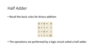
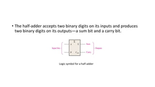
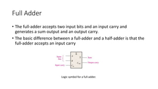
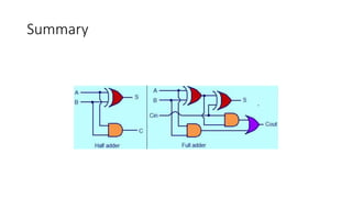
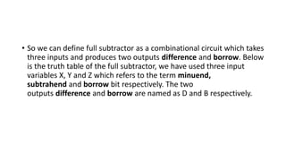
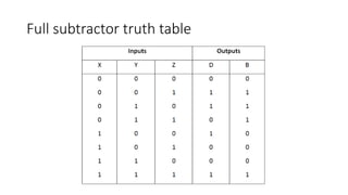
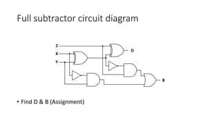
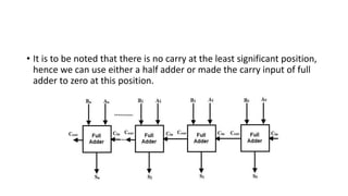
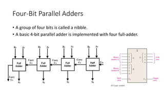
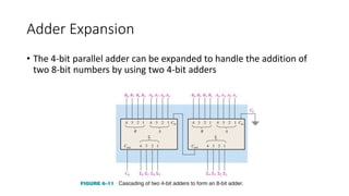
Half and Full Adders
Half Adder
• Recall the basic rules for binary addition
• The operations are performed by a logic circuit called a half-adder
• The half-adder accepts two binary digits on its inputs and produces
two binary digits on its outputs—a sum bit and a carry bit.
Logic symbol for a half-adder
• Now observe that the sum output is a 1 only if the input variables, A
and B, are not equal. The sum can therefore be expressed as the
exclusive-OR of the input variables.
• Notice that the output carry is a 1 only when both A and B are 1s;
therefore, Cout can be expressed as the AND of the input variables.
Logic Diagram
Full Adder
• The full-adder accepts two input bits and an input carry and
generates a sum output and an output carry.
• The basic difference between a full-adder and a half-adder is that the
full-adder accepts an input carry
Logic symbol for a full-adder.
Implementation of Full Adder using Half
Adders
• 2 Half Adders and a OR gate is required to implement a Full Adder.
Implementation of Full Adder using Half
Adders
Summary
Half Subtractor
• As like addition operation of 2 binary digits, which produces SUM and
CARRY, the subtraction of 2 binary digits also produces two outputs
which are termed as difference and borrow. The simplest possible
subtraction of 2-bit binary digits consists of four possible operations,
they are 0-0, 0-1, 1-0 and 1-1. The operations 0-0, 1-0 and 1-
1 produces a subtraction of 1-bit output whereas, the remaining
operation 0-1 produces a 2-bit output. They are referred
as difference and borrow bit respectively. This borrow bit is used for
subtraction of the next higher pair bit.
• So, we can define half subtractor as a combinational circuit which is
capable of performing subtraction of 2-bit binary digits is known as a
half subtractor. Here, the binary digit from which the other digit is
subtracted is called minuend and the binary digit which is to be
subtracted is known as the subtrahend.
Half subtractor truth table :
Half subtractor circuit diagram
Full Subtractor
• When there is a situation where the minuend and subtrahend
number contains more significant bit, then the borrow bit which is
obtained from the subtraction of 2-bit binary digits is subtracted from
the next higher order pair of bits. In such situation, the subtraction
involves the operation of 3 bits. Such situation of subtraction can’t
handle by a simple half subtractor. So, combining two half subtractor
we can form another combinational circuit which can perform this
type of operation. This circuit is known as the full subtractor.
• So we can define full subtractor as a combinational circuit which takes
three inputs and produces two outputs difference and borrow. Below
is the truth table of the full subtractor, we have used three input
variables X, Y and Z which refers to the term minuend,
subtrahend and borrow bit respectively. The two
outputs difference and borrow are named as D and B respectively.
Full subtractor truth table
Full subtractor circuit diagram
• Find D & B (Assignment)
Parallel Binary Adders
• As we discussed that a single full adder performs the addition of two
one bit numbers and an input carry.
• For performing the addition of binary numbers with more than one
bit, more than one full adder is required depends on the number bits.
• Thus, a parallel adder is used for adding all bits of the two numbers
simultaneously.
• By connecting a number of full adders in parallel, n-bit parallel adder
is constructed.
• It is to be noted that there is no carry at the least significant position,
hence we can use either a half adder or made the carry input of full
adder to zero at this position.
Four-Bit Parallel Adders
• A group of four bits is called a nibble.
• A basic 4-bit parallel adder is implemented with four full-adder.
• The two binary numbers to be added are A3A2A1A0 and B3B2B1B0
which are applied to the corresponding inputs of full adders.
• This parallel adder produces their sum as C4S3S2S1S0 where C4 is the
final carry.
• In the 4 bit adder, first block is a half-adder(Or, Full adder) that has
two inputs as A0B0 and produces their sum S0 and a carry bit C1.
Next block should be full adder as there are three inputs applied to it.
Hence this full adder produces their sum S1 and a carry C2. This will
be followed by other two full adders and thus the final sum is
C4S3S2S1S0.
• Most commonly Full adders are designed in dual in-line package
integrated circuits.
• A typical 74LS283 is a 4 bit full adder.
• Arithmetic and Logic Unit of a unit computer consist of these parallel
adders to perform the addition of binary numbers.
Adder Expansion
• The 4-bit parallel adder can be expanded to handle the addition of
two 8-bit numbers by using two 4-bit adders
Ripple carry and Look-ahead carry
• Parallel adders can be placed into two categories based on the way in
which internal carries from stage to stage are handled.
• Those categories are ripple carry and look-ahead carry.
• Externally, both types of adders are the same in terms of inputs and
outputs.
• The difference is the speed at which they can add numbers.
• The lookahead carry adder is much faster than the ripple carry adder

Adder & subtractor (Half adder, Full adder, Half subtractor, Full subtractor)

  • 1.
  • 2.
    Half Adder • Recallthe basic rules for binary addition • The operations are performed by a logic circuit called a half-adder
  • 3.
    • The half-adderaccepts two binary digits on its inputs and produces two binary digits on its outputs—a sum bit and a carry bit. Logic symbol for a half-adder
  • 4.
    • Now observethat the sum output is a 1 only if the input variables, A and B, are not equal. The sum can therefore be expressed as the exclusive-OR of the input variables. • Notice that the output carry is a 1 only when both A and B are 1s; therefore, Cout can be expressed as the AND of the input variables.
  • 5.
  • 6.
    Full Adder • Thefull-adder accepts two input bits and an input carry and generates a sum output and an output carry. • The basic difference between a full-adder and a half-adder is that the full-adder accepts an input carry Logic symbol for a full-adder.
  • 9.
    Implementation of FullAdder using Half Adders • 2 Half Adders and a OR gate is required to implement a Full Adder.
  • 10.
    Implementation of FullAdder using Half Adders
  • 11.
  • 12.
    Half Subtractor • Aslike addition operation of 2 binary digits, which produces SUM and CARRY, the subtraction of 2 binary digits also produces two outputs which are termed as difference and borrow. The simplest possible subtraction of 2-bit binary digits consists of four possible operations, they are 0-0, 0-1, 1-0 and 1-1. The operations 0-0, 1-0 and 1- 1 produces a subtraction of 1-bit output whereas, the remaining operation 0-1 produces a 2-bit output. They are referred as difference and borrow bit respectively. This borrow bit is used for subtraction of the next higher pair bit. • So, we can define half subtractor as a combinational circuit which is capable of performing subtraction of 2-bit binary digits is known as a half subtractor. Here, the binary digit from which the other digit is subtracted is called minuend and the binary digit which is to be subtracted is known as the subtrahend.
  • 13.
  • 14.
  • 15.
    Full Subtractor • Whenthere is a situation where the minuend and subtrahend number contains more significant bit, then the borrow bit which is obtained from the subtraction of 2-bit binary digits is subtracted from the next higher order pair of bits. In such situation, the subtraction involves the operation of 3 bits. Such situation of subtraction can’t handle by a simple half subtractor. So, combining two half subtractor we can form another combinational circuit which can perform this type of operation. This circuit is known as the full subtractor.
  • 16.
    • So wecan define full subtractor as a combinational circuit which takes three inputs and produces two outputs difference and borrow. Below is the truth table of the full subtractor, we have used three input variables X, Y and Z which refers to the term minuend, subtrahend and borrow bit respectively. The two outputs difference and borrow are named as D and B respectively.
  • 17.
  • 18.
    Full subtractor circuitdiagram • Find D & B (Assignment)
  • 19.
    Parallel Binary Adders •As we discussed that a single full adder performs the addition of two one bit numbers and an input carry. • For performing the addition of binary numbers with more than one bit, more than one full adder is required depends on the number bits. • Thus, a parallel adder is used for adding all bits of the two numbers simultaneously. • By connecting a number of full adders in parallel, n-bit parallel adder is constructed.
  • 20.
    • It isto be noted that there is no carry at the least significant position, hence we can use either a half adder or made the carry input of full adder to zero at this position.
  • 21.
    Four-Bit Parallel Adders •A group of four bits is called a nibble. • A basic 4-bit parallel adder is implemented with four full-adder.
  • 22.
    • The twobinary numbers to be added are A3A2A1A0 and B3B2B1B0 which are applied to the corresponding inputs of full adders. • This parallel adder produces their sum as C4S3S2S1S0 where C4 is the final carry. • In the 4 bit adder, first block is a half-adder(Or, Full adder) that has two inputs as A0B0 and produces their sum S0 and a carry bit C1. Next block should be full adder as there are three inputs applied to it. Hence this full adder produces their sum S1 and a carry C2. This will be followed by other two full adders and thus the final sum is C4S3S2S1S0.
  • 23.
    • Most commonlyFull adders are designed in dual in-line package integrated circuits. • A typical 74LS283 is a 4 bit full adder. • Arithmetic and Logic Unit of a unit computer consist of these parallel adders to perform the addition of binary numbers.
  • 24.
    Adder Expansion • The4-bit parallel adder can be expanded to handle the addition of two 8-bit numbers by using two 4-bit adders
  • 25.
    Ripple carry andLook-ahead carry • Parallel adders can be placed into two categories based on the way in which internal carries from stage to stage are handled. • Those categories are ripple carry and look-ahead carry. • Externally, both types of adders are the same in terms of inputs and outputs. • The difference is the speed at which they can add numbers. • The lookahead carry adder is much faster than the ripple carry adder