Downloaded 159 times
![Sequential Logic
Circuit
Yong Heui Cho @ Mokwon University
Most of slides are referred to and all credits should go to:
[1] M.Y. Idris & N.M. Noor, Sequential Circuit, slideshare.](https://image.slidesharecdn.com/5-151008084901-lva1-app6892/85/Sequential-Logic-Circuit-1-320.jpg)
![Sequential Logic
Circuit
Yong Heui Cho @ Mokwon University
Most of slides are referred to and all credits should go to:
[1] M.Y. Idris & N.M. Noor, Sequential Circuit, slideshare.](https://image.slidesharecdn.com/5-151008084901-lva1-app6892/75/Sequential-Logic-Circuit-1-2048.jpg)

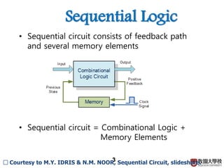
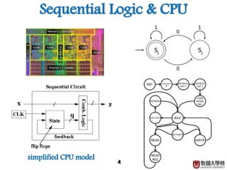
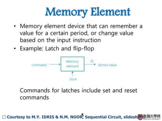
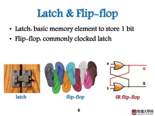
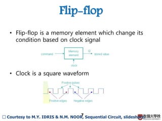
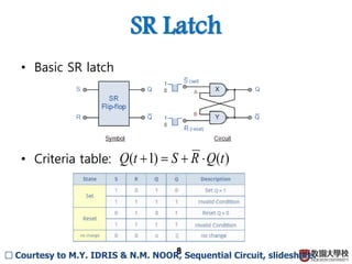
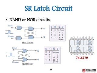
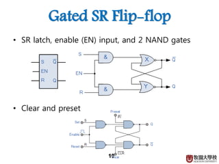
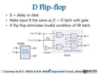
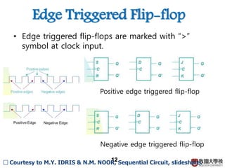
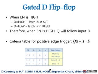
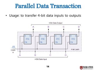
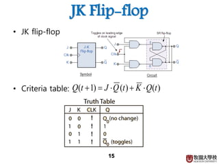
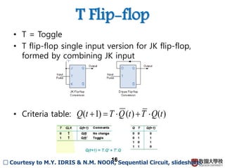
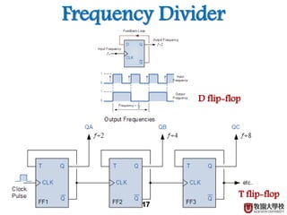
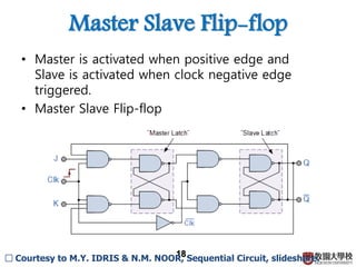

1) Sequential circuits consist of combinational logic and memory elements like latches and flip-flops. 2) Memory elements can store digital values and change their values based on input signals like clock signals. Common memory elements include latches, D flip-flops, JK flip-flops, and T flip-flops. 3) Sequential circuits are important building blocks of CPUs as they allow for the storage and processing of digital signals over time.


![16148_flip-flopaaaaaaaaaaaaaaaaa1[1].ppt](https://cdn.slidesharecdn.com/ss_thumbnails/16148flip-flop11-241007142703-8f186e77-thumbnail.jpg?width=640&height=640&fit=bounds)


