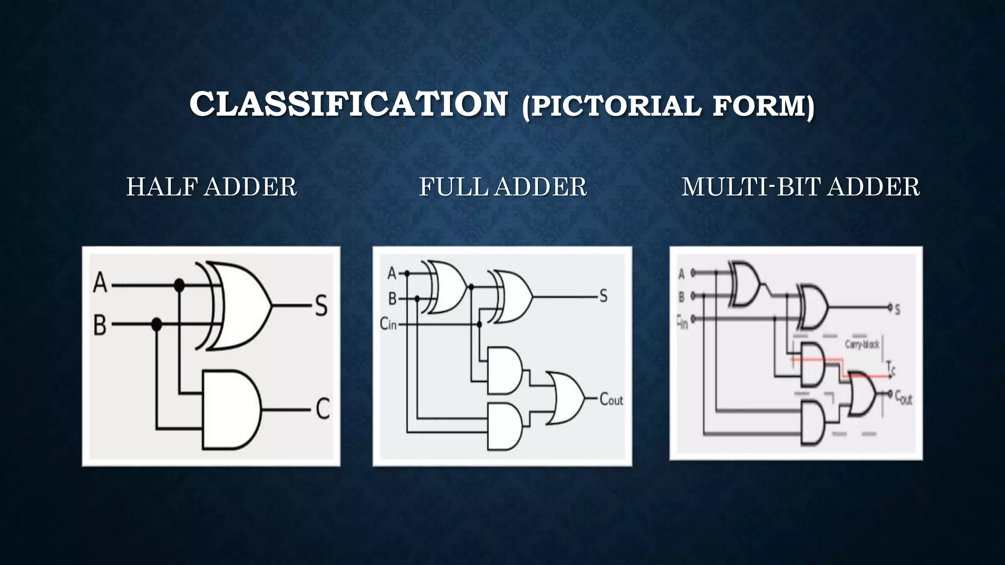
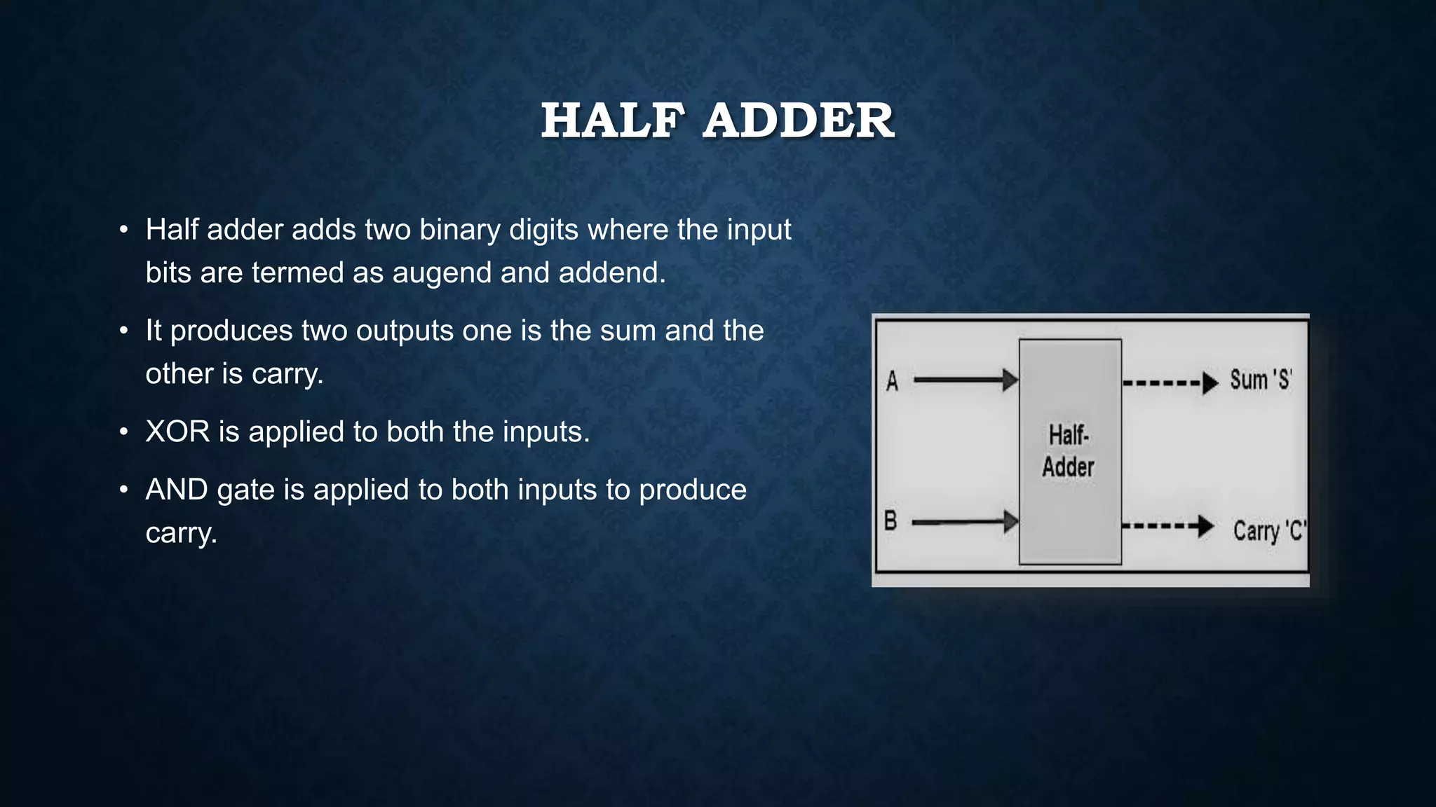
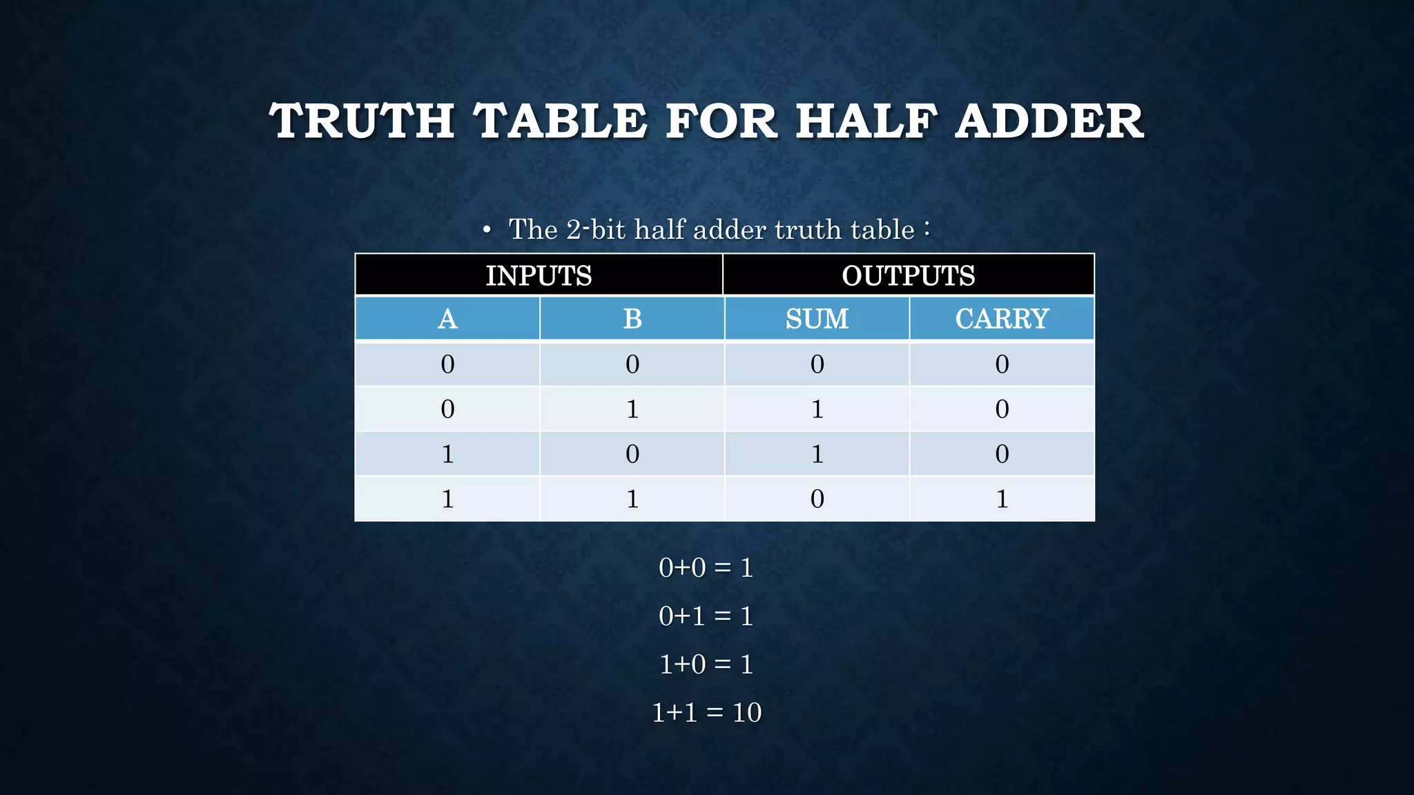
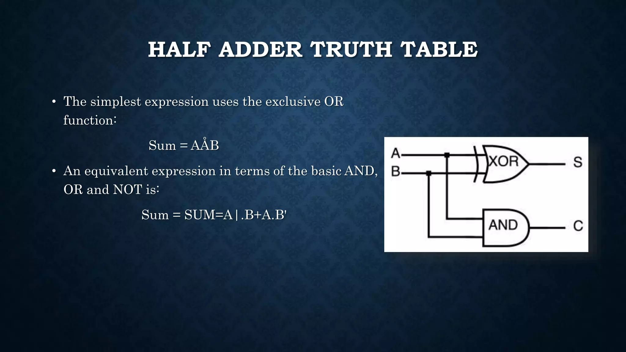
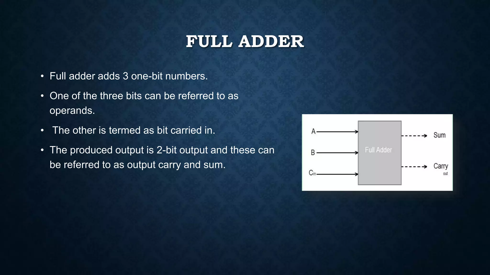
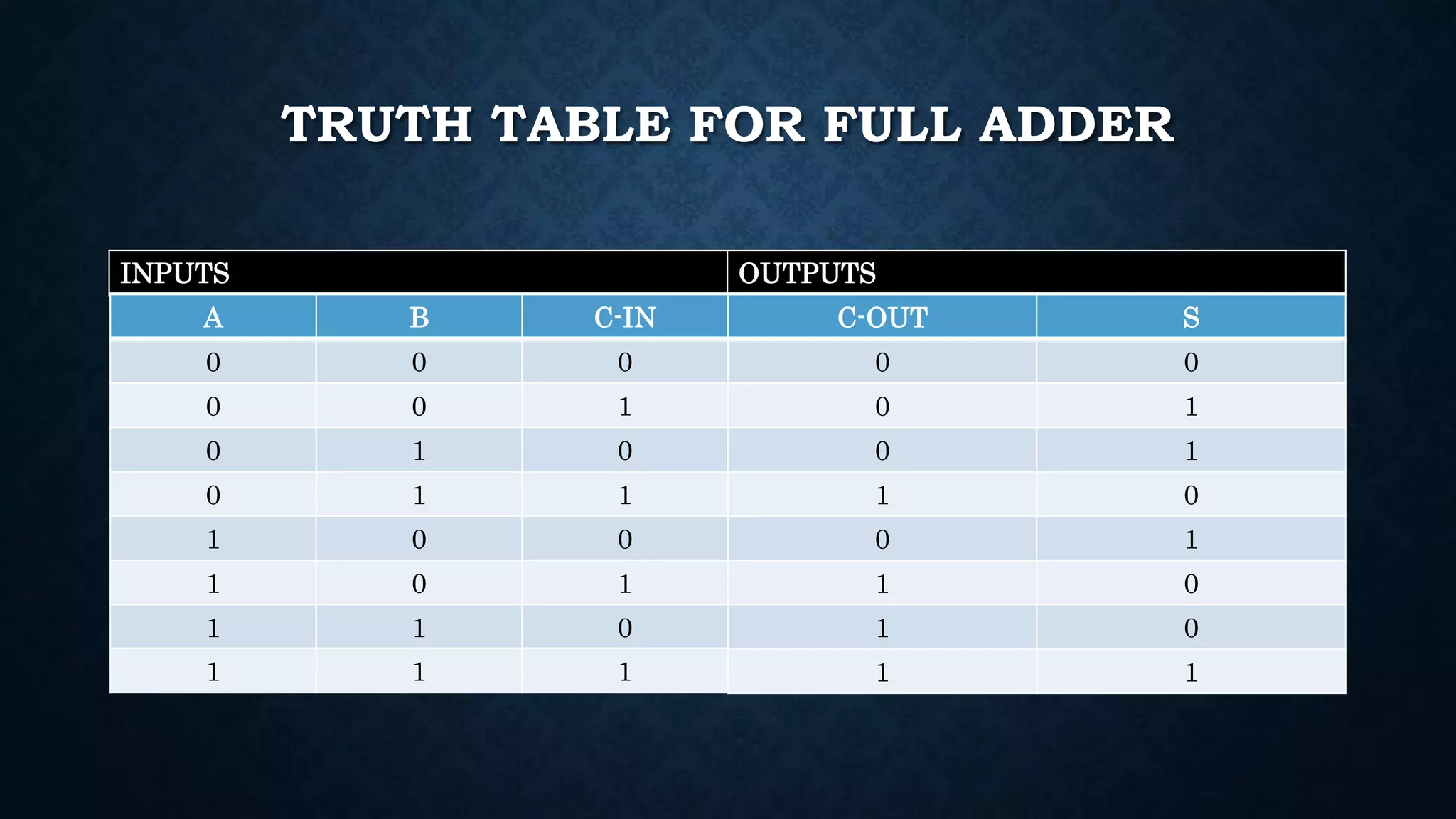
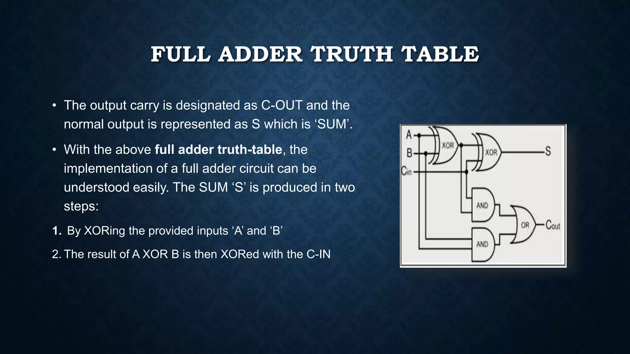
INTRODUCTION
An adder is a digital logic circuit in electronics that is extensively used for the addition of
numbers. In many computers and other types of processors, adders are even used to
calculate addresses and related activities and calculate table indices in the ALU and even
utilized in other parts of the processors. These can be built for many numerical
representations like excess-3 or binary coded decimal.
Adders are basically classified into two types: Half Adder and Full Adder.
CLASSIFICATION OF ADDERS
Adders are broadly classified into two types. They are:
• Half Adder
• Full Adder
• Multi-bit Adder
Half Adder
Half Adder is a combinational arithmetic circuit that adds two binary numbers and produces sum bit
(S) and carry bit (C) as the output. It is used to add 2 single-bit binary numbers.
Full Adder
It is a combinational arithmetic circuit constructed by combining two Half Adder circuits. It is used
to add 3 one-bit binary numbers.
Multi-bit Adder
Multi-bit Adders are constructed using Full Adders either Serially or in Parallel known as: Parallel Adder
and Serial Adder
CLASSIFICATION (PICTORIAL FORM)
HALF ADDER FULL ADDER MULTI-BIT ADDER
HALF ADDER
• Half adder adds two binary digits where the input
bits are termed as augend and addend.
• It produces two outputs one is the sum and the
other is carry.
• XOR is applied to both the inputs.
• AND gate is applied to both inputs to produce
carry.
TRUTH TABLE FOR HALF ADDER
• The 2-bit half adder truth table :
0+0 = 1
0+1 = 1
1+0 = 1
1+1 = 10
INPUTS OUTPUTS
A B SUM CARRY
0 0 0 0
0 1 1 0
1 0 1 0
1 1 0 1
HALF ADDER TRUTH TABLE
• The simplest expression uses the exclusive OR
function:
Sum = AÅB
• An equivalent expression in terms of the basic AND,
OR and NOT is:
Sum = SUM=A|.B+A.B'
FULL ADDER
• Full adder adds 3 one-bit numbers.
• One of the three bits can be referred to as
operands.
• The other is termed as bit carried in.
• The produced output is 2-bit output and these can
be referred to as output carry and sum.
TRUTH TABLE FOR FULL ADDER
INPUTS OUTPUTS
A B C-IN
0 0 0
0 0 1
0 1 0
0 1 1
1 0 0
1 0 1
1 1 0
1 1 1
C-OUT S
0 0
0 1
0 1
1 0
0 1
1 0
1 0
1 1
FULL ADDER TRUTH TABLE
• The output carry is designated as C-OUT and the
normal output is represented as S which is ‘SUM’.
• With the above full adder truth-table, the
implementation of a full adder circuit can be
understood easily. The SUM ‘S’ is produced in two
steps:
1. By XORing the provided inputs ‘A’ and ‘B’
2. The result of A XOR B is then XORed with the C-IN
THE RELATION BETWEEN
HALF ADDER AND FULL ADDER
• Half adder produces results and full adder uses half adder to produce some other
results.
• Similarly, the full adder is of two half adders.
• The Full-Adder is the actual block that we use to create the arithmetic circuits.
Half adder and full adder

Half adder and full adder

  • 2.
    INTRODUCTION An adder isa digital logic circuit in electronics that is extensively used for the addition of numbers. In many computers and other types of processors, adders are even used to calculate addresses and related activities and calculate table indices in the ALU and even utilized in other parts of the processors. These can be built for many numerical representations like excess-3 or binary coded decimal. Adders are basically classified into two types: Half Adder and Full Adder.
  • 3.
    CLASSIFICATION OF ADDERS Addersare broadly classified into two types. They are: • Half Adder • Full Adder • Multi-bit Adder Half Adder Half Adder is a combinational arithmetic circuit that adds two binary numbers and produces sum bit (S) and carry bit (C) as the output. It is used to add 2 single-bit binary numbers. Full Adder It is a combinational arithmetic circuit constructed by combining two Half Adder circuits. It is used to add 3 one-bit binary numbers. Multi-bit Adder Multi-bit Adders are constructed using Full Adders either Serially or in Parallel known as: Parallel Adder and Serial Adder
  • 4.
    CLASSIFICATION (PICTORIAL FORM) HALFADDER FULL ADDER MULTI-BIT ADDER
  • 5.
    HALF ADDER • Halfadder adds two binary digits where the input bits are termed as augend and addend. • It produces two outputs one is the sum and the other is carry. • XOR is applied to both the inputs. • AND gate is applied to both inputs to produce carry.
  • 6.
    TRUTH TABLE FORHALF ADDER • The 2-bit half adder truth table : 0+0 = 1 0+1 = 1 1+0 = 1 1+1 = 10 INPUTS OUTPUTS A B SUM CARRY 0 0 0 0 0 1 1 0 1 0 1 0 1 1 0 1
  • 7.
    HALF ADDER TRUTHTABLE • The simplest expression uses the exclusive OR function: Sum = AÅB • An equivalent expression in terms of the basic AND, OR and NOT is: Sum = SUM=A|.B+A.B'
  • 8.
    FULL ADDER • Fulladder adds 3 one-bit numbers. • One of the three bits can be referred to as operands. • The other is termed as bit carried in. • The produced output is 2-bit output and these can be referred to as output carry and sum.
  • 9.
    TRUTH TABLE FORFULL ADDER INPUTS OUTPUTS A B C-IN 0 0 0 0 0 1 0 1 0 0 1 1 1 0 0 1 0 1 1 1 0 1 1 1 C-OUT S 0 0 0 1 0 1 1 0 0 1 1 0 1 0 1 1
  • 10.
    FULL ADDER TRUTHTABLE • The output carry is designated as C-OUT and the normal output is represented as S which is ‘SUM’. • With the above full adder truth-table, the implementation of a full adder circuit can be understood easily. The SUM ‘S’ is produced in two steps: 1. By XORing the provided inputs ‘A’ and ‘B’ 2. The result of A XOR B is then XORed with the C-IN
  • 11.
    THE RELATION BETWEEN HALFADDER AND FULL ADDER • Half adder produces results and full adder uses half adder to produce some other results. • Similarly, the full adder is of two half adders. • The Full-Adder is the actual block that we use to create the arithmetic circuits.