Download as PDF, PPTX
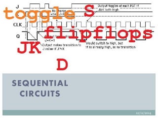
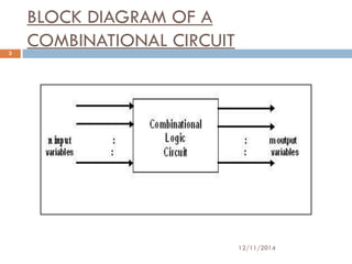


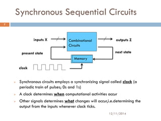


This document discusses sequential and combinational circuits. Combinational circuits are made of logic gates and their outputs depend only on the current inputs. Sequential circuits contain memory elements like flip-flops in addition to combinational logic, so their outputs depend on current inputs and the circuit's previous state. There are two types of sequential circuits: synchronous use a clock signal to control state changes while asynchronous circuits change state directly in response to input changes.


![16148_flip-flopaaaaaaaaaaaaaaaaa1[1].ppt](https://cdn.slidesharecdn.com/ss_thumbnails/16148flip-flop11-241007142703-8f186e77-thumbnail.jpg?width=640&height=640&fit=bounds)