Download to read offline


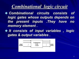
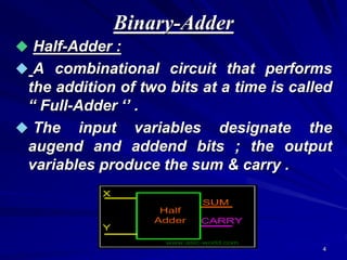
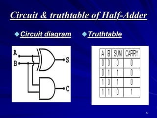
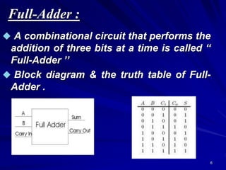
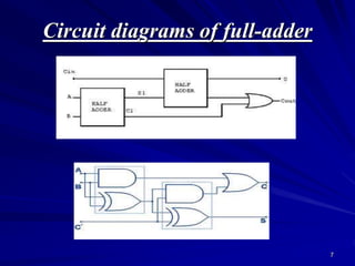
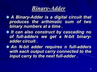
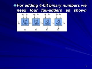
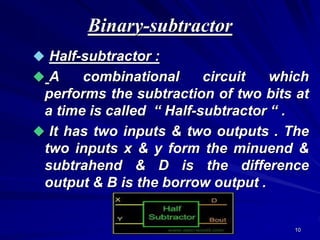
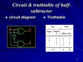
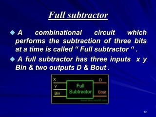
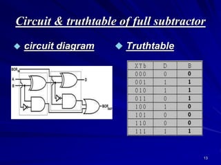
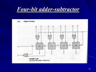

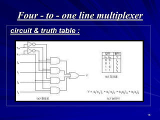


This document provides an overview of combinational logic circuits such as adders, subtractors, and multiplexers. It describes half adders and full adders that perform binary addition of two and three bits respectively. Binary adders can be constructed by cascading full adders. Binary subtractors use half and full subtractors to perform subtraction by taking the 2's complement of one number and adding it to the other. An example circuit is shown that can function as either an adder or subtractor based on a mode input. Finally, multiplexers are described as circuits that select one of several input lines to output based on selection lines.