Downloaded 1,032 times


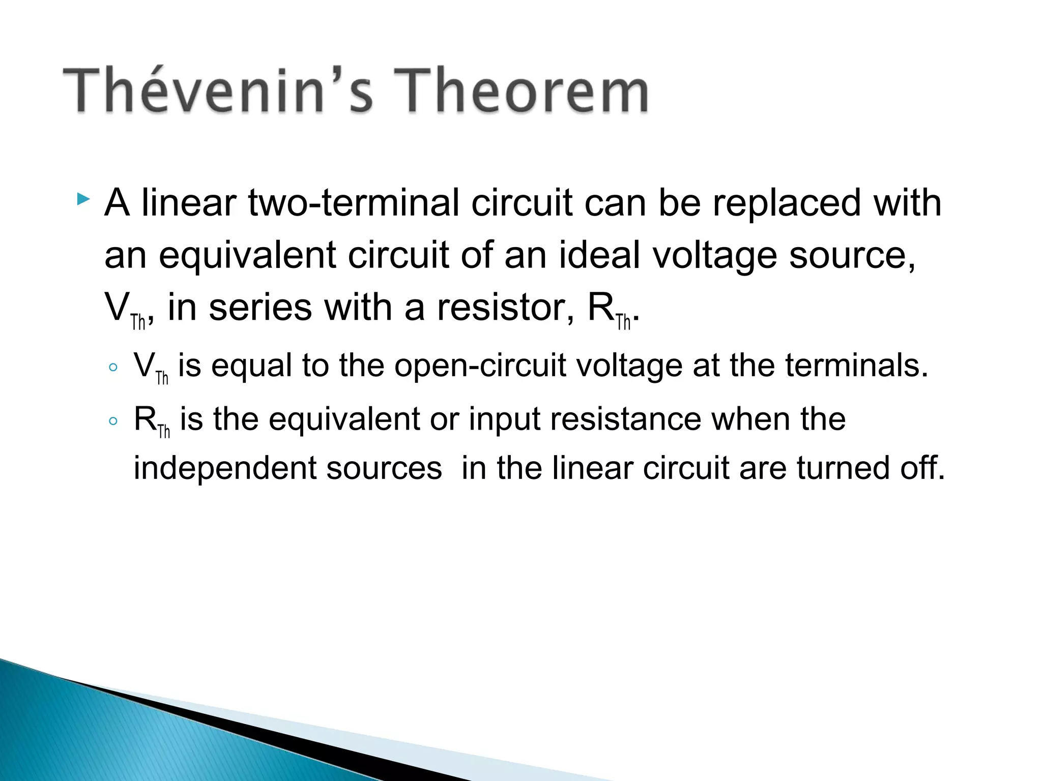
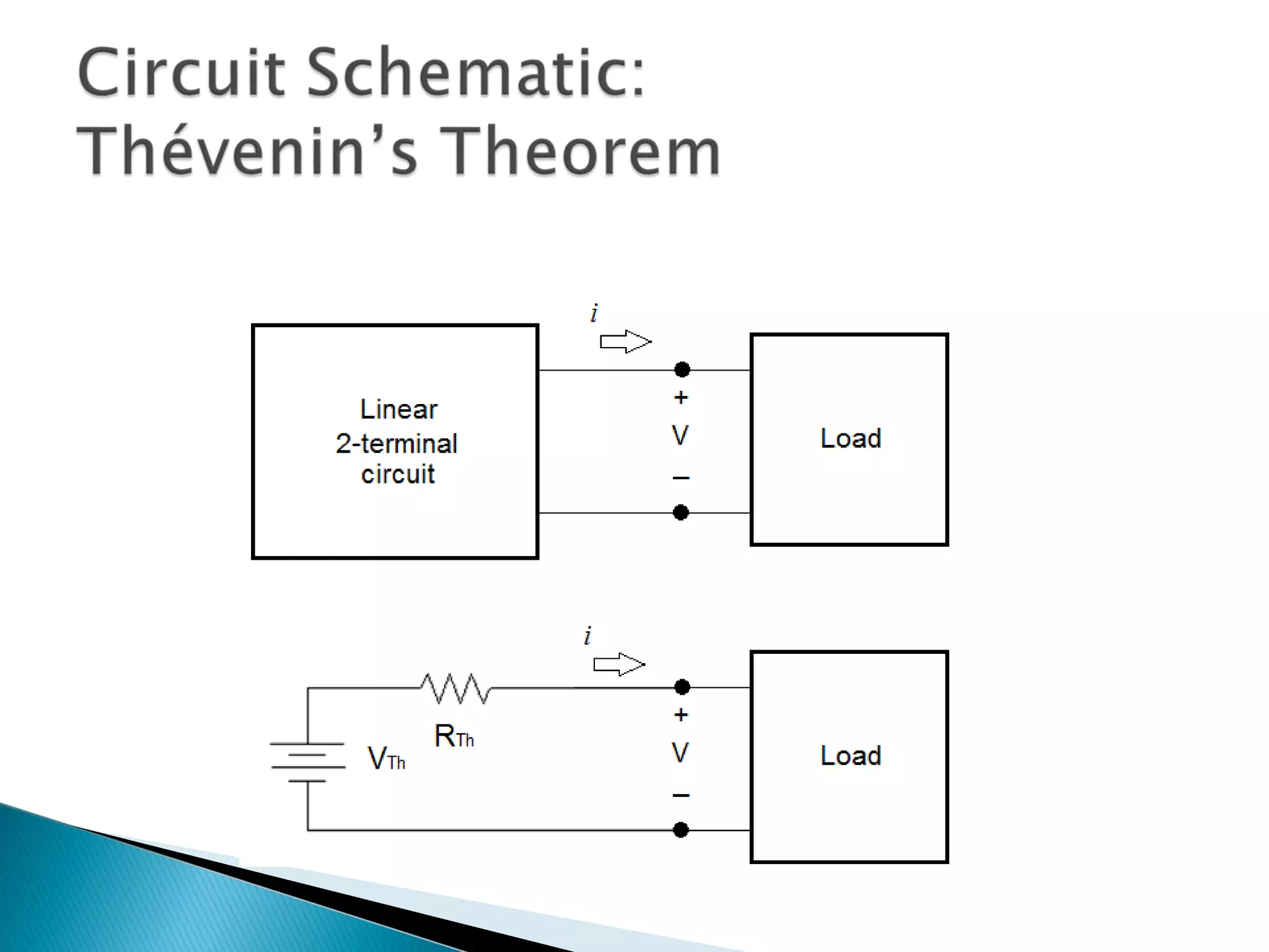
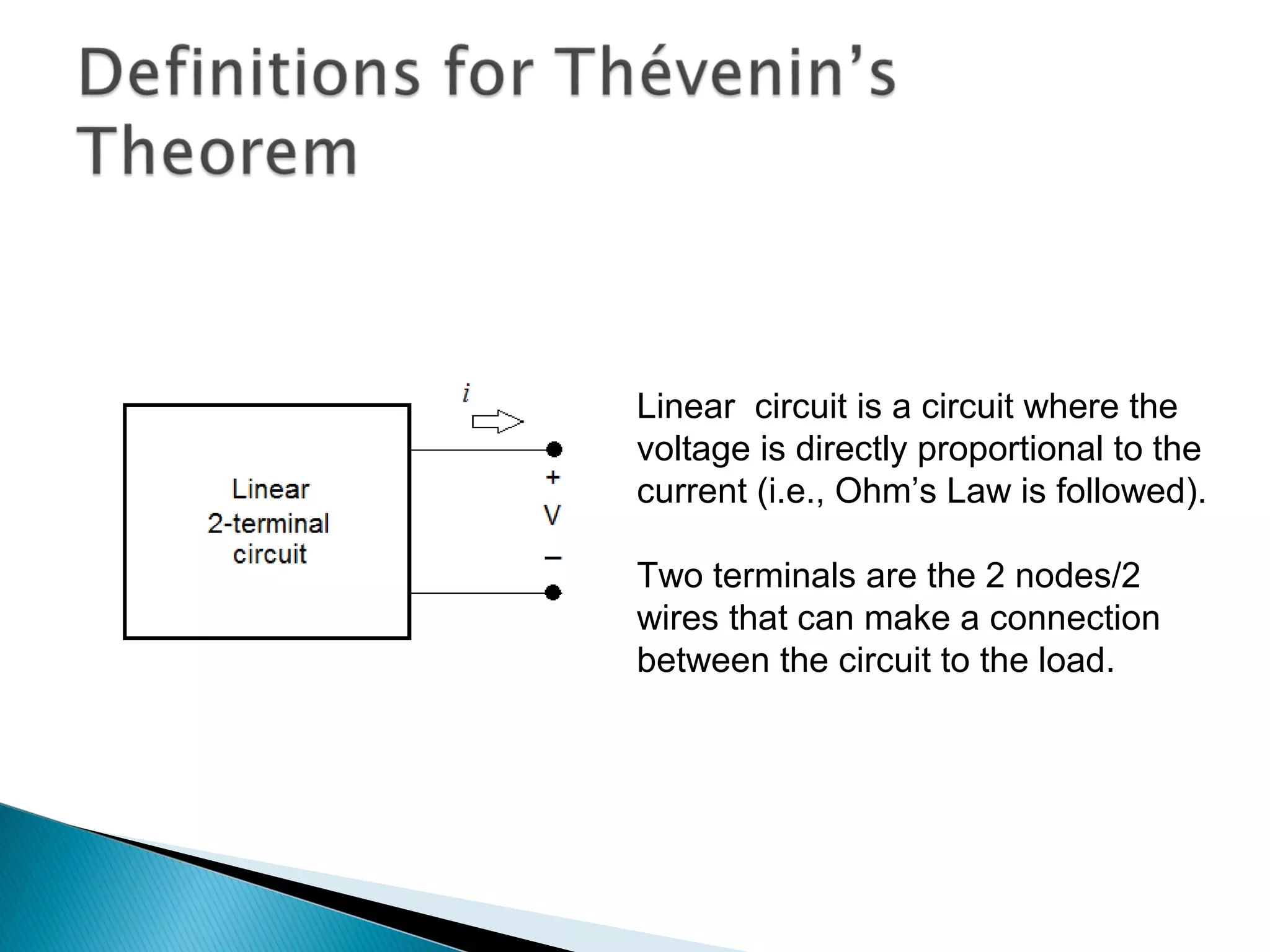
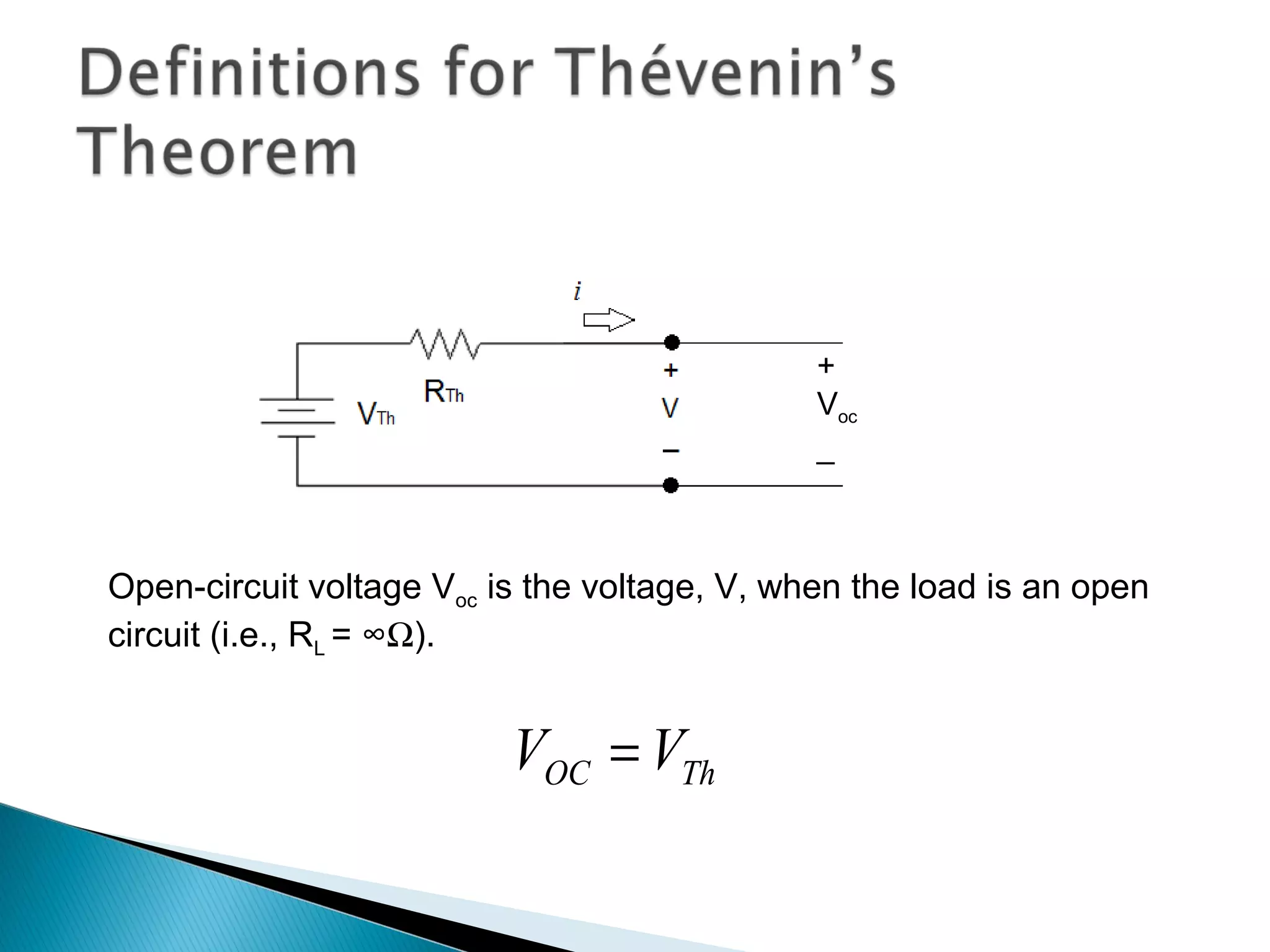
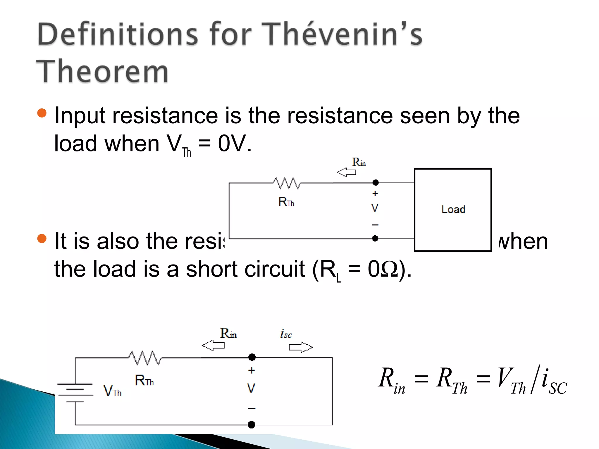
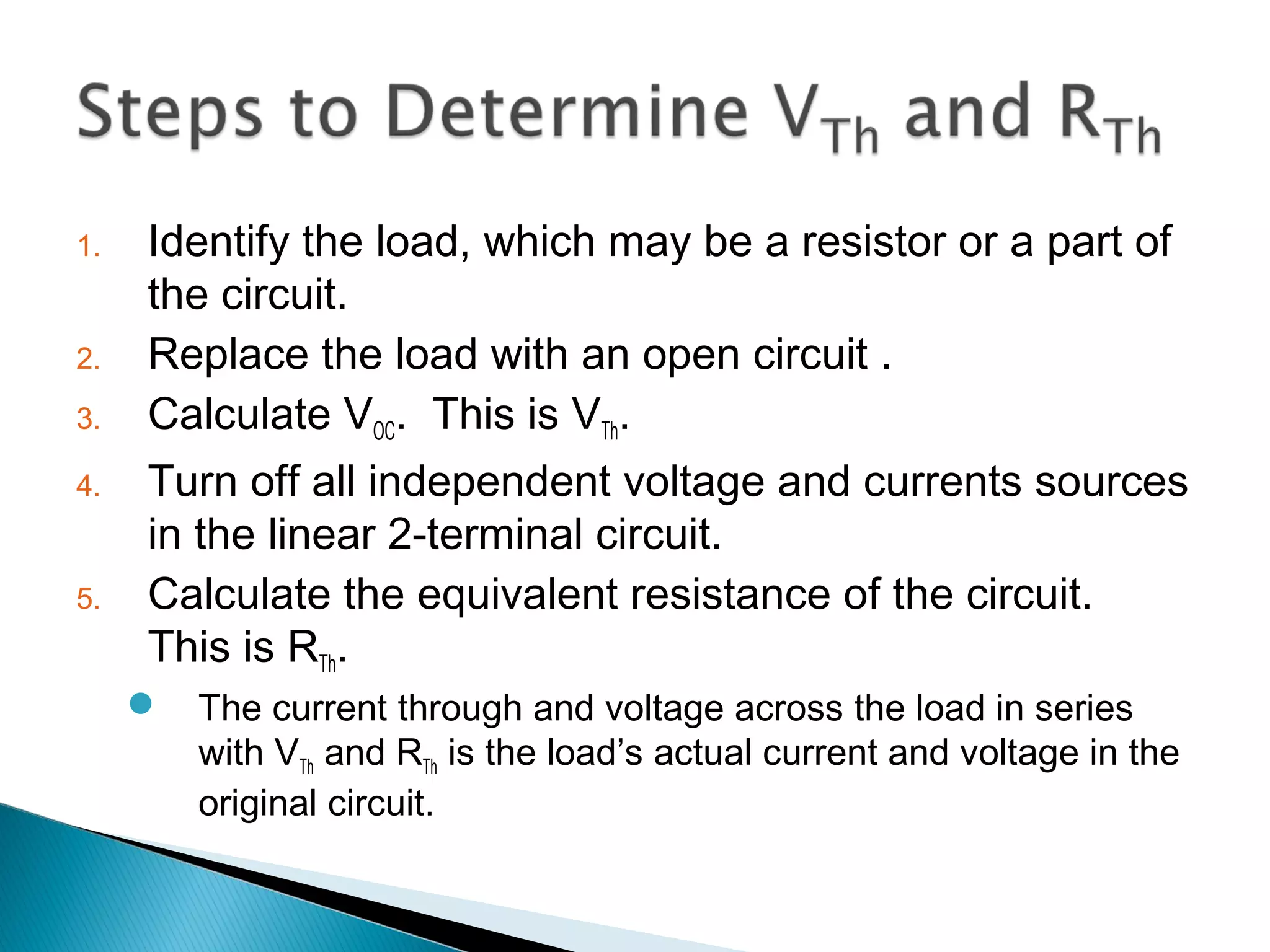
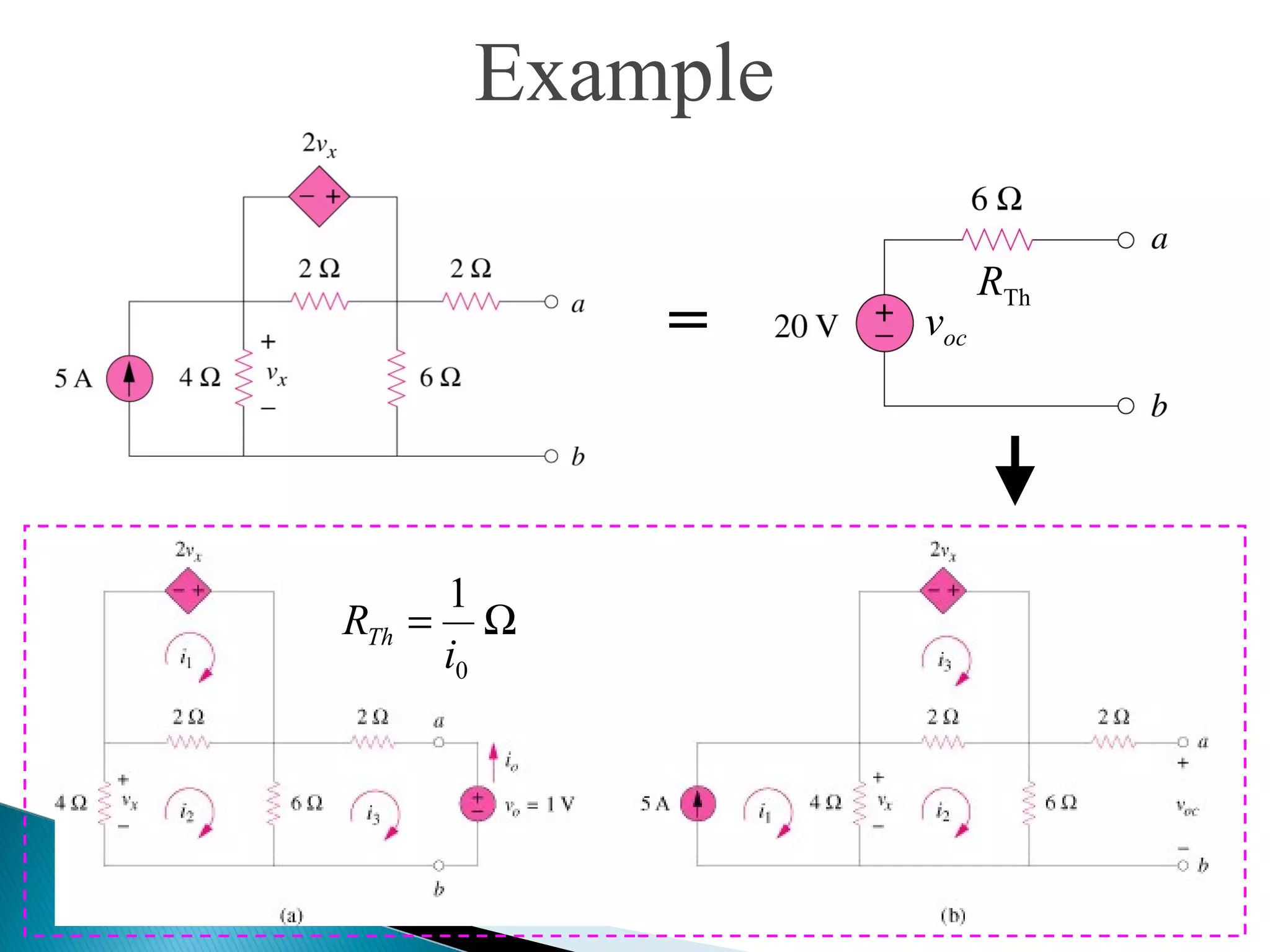

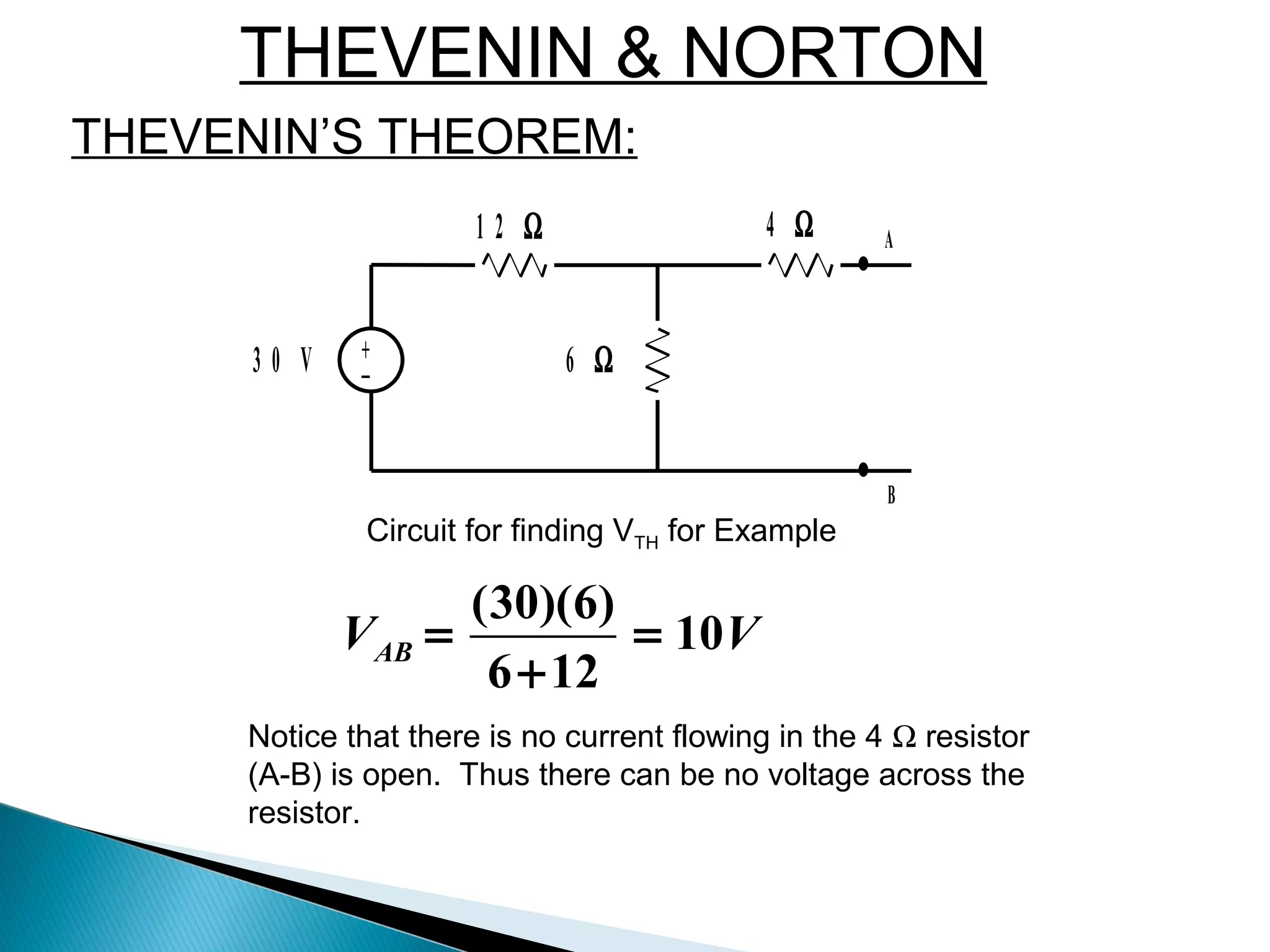

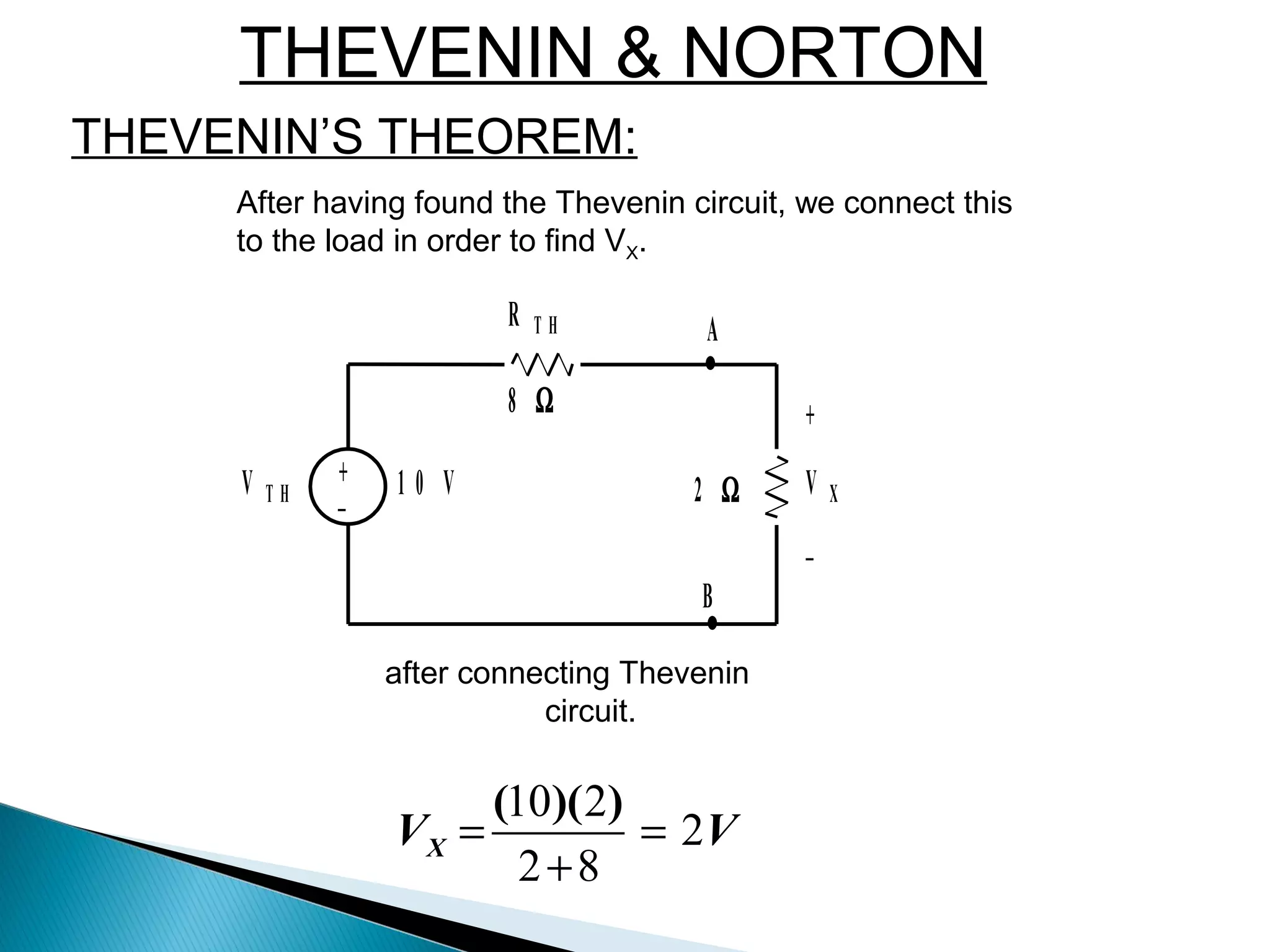
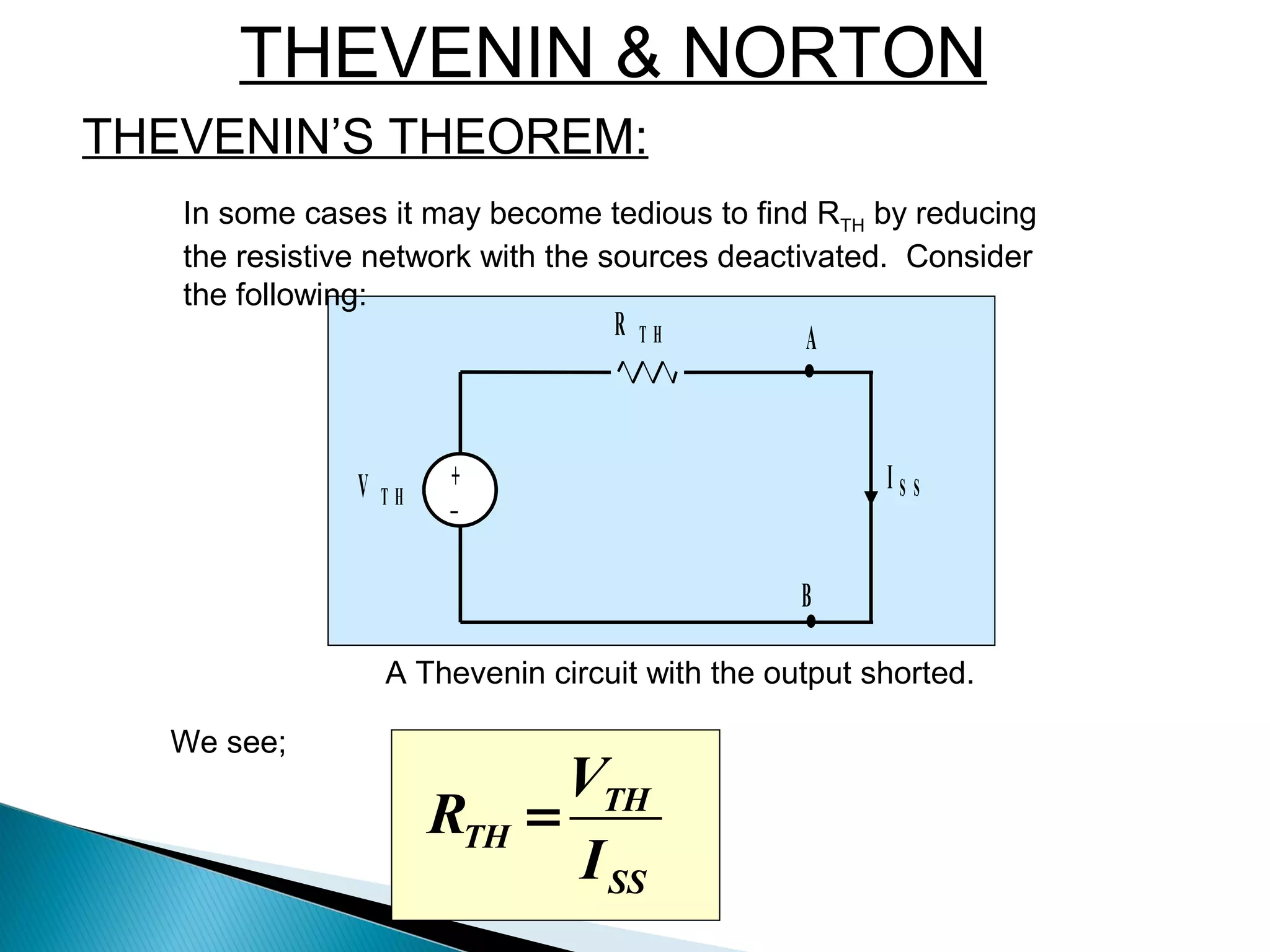


Thévenin's theorem states that any linear two-terminal circuit can be replaced by an equivalent circuit consisting of an ideal voltage source (VTh) in series with a resistor (RTh). VTh is equal to the open-circuit voltage at the terminals and RTh is the equivalent input resistance when independent sources are turned off. To find the Thevenin equivalent circuit, first the load is replaced with an open circuit to find VTh, then independent sources are turned off to find RTh, the resistance seen looking into the terminals. Once the Thevenin equivalent circuit is determined, it can be used to solve for voltages and currents in the original circuit.


