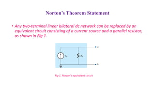
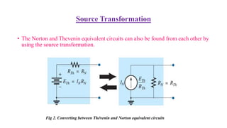
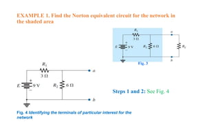
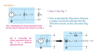
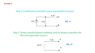
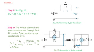
Norton’s Theorem
By-
Rajni Maurya
MITS, Gwalior
rajni.maurya2790@gmail.com
Norton’s Theorem Statement
• Any two-terminal linear bilateral dc network can be replaced by an
equivalent circuit consisting of a current source and a parallel resistor,
as shown in Fig 1.
Fig 1. Norton’s equivalent circuit
Calculating the Norton equivalent
• The steps leading to the proper values of IN and RN
 PRELIMINARY
STEP 1. Remove that portion of the network across
which the Norton equivalent circuit is found
STEP 2. Mark the terminals of the remaining two-
terminal network
 RN:
STEP 3. Calculate RN by first setting all sources to zero (voltage sources are
replaced with short circuits, and current sources with open circuits) and then
finding the resultant resistance between the two marked terminals.
(If the internal resistance of the voltage and/or current sources is included in
the original network, it must remain when the sources are set to zero.)
Since RN = RTh , the procedure and value obtained using the approach
described for Thévenin’s theorem will determine the proper value of RN
Calculating the Norton equivalent
 IN :
STEP 4. Calculate IN by first returning all the sources to their original
position and then finding the short-circuit current between the marked
terminals. It is the same current that would be measured by an ammeter
placed between the marked terminals.
 Conclusion:
STEP 5. Draw the Norton equivalent circuit with the portion of the
circuit previously removed replaced between the terminals of the
equivalent circuit.
Calculating the Norton equivalent
Source Transformation
• The Norton and Thevenin equivalent circuits can also be found from each other by
using the source transformation.
Fig 2. Converting between Thévenin and Norton equivalent circuits
EXAMPLE 1. Find the Norton equivalent circuit for the network in
the shaded area
Fig. 4 Identifying the terminals of particular interest for the
network
Fig. 3
Steps 1 and 2: See Fig. 4
• Step 3: See Fig. 5, and
• 𝑅 𝑁 = R1 || R2 = 3 || 6 =
(3)(6)
3+6
= 2Ω
EXAMPLE 1.
Step 4: See Fig. 6, the short-circuit connection
between terminals a and b is in parallel with 𝑅2 and
eliminates its effect. 𝐼 𝑁 is therefore the same as
through 𝑅1 , and the full battery voltage appears
across R1 since
𝑉2 = 𝐼2 𝑅2 = (0)6 = 0 V
Therefore,
𝐼 𝑁 =
𝐸
𝑅 𝑁
=
9
3
= 3 𝐴
Fig. 5 Determining
𝑅 𝑁 for the network
Fig. 6 Determining 𝐼 𝑁 for the network
• Step 5: See Fig. 7
• Now to develop the Thévenin’s theorem,
a simple conversion indicates that the
Thevenin circuits, in fact, the same (Fig.
8).
EXAMPLE 1.
Fig 7. Substituting the Norton equivalent circuit
for the network external to the resistor 𝑅 𝐿 in Fig. 3
Fig 8. Converting the
Norton equivalent circuit in
Fig. 7 to a Thévenin
equivalent circuit
Example 2. Derive the Norton equivalent of the circuit in fig. 9
Solution
Step 1: Source transformation (The 25V voltage source is converted to a
5 A currentsource.)
25V
20 3A
5 4
a
b
20 3 A5
4
a
b
5A
FIG 9.
FIG 10.
48 A
4
a
Step 3: Source transformation (combined serial resistance to produce the
Thevenin equivalent circuit.)
8
32 V
a
b
Step 2: Combination of parallel source and parallel resistance
Example 2.
FIG. 11
b
FIG. 12
8
Ω
a
b
Fig 13. Norton equivalent circuit
4
A
Step 4: Source transformation (To produce the Norton equivalent circuit.
The current source is 4A
I =
𝑉
𝑅
=
32
8
= 4 𝐴
Example 2.
EXAMPLE 3. Find the Norton equivalent circuit for the network external to
the 9Ω resistor.
Solution:
Steps 1 and 2: See Fig. 15
Fig. 15
Identifying the terminals of particular interest for the network
Fig. 14
Step 3: See Fig. 16
𝑅 𝑁 = R1 + R2 = 5 + 4 = 9 Ω
Fig. 16 Determining 𝑅 𝑁 for the network
Step 4: The Norton current is the
same as the current through the 4
Ω resistor. Applying the current
divider rule gives
𝐼 𝑁 =
𝐼. 𝑅1
𝑅1 + 𝑅2
=
(5)(10)
5 + 4
=
50
9
= 5.56 𝐴
Fig. 17 Determining 𝐼 𝑁 for the network
Example 3.
• Step 5: See Fig. 18
Fig. 18 Substituting the Norton equivalent circuit for the
network external to the resistor 𝑅 𝑁 in Fig. 14
Example 3.
THANKS

Norton's theorem

  • 1.
    Norton’s Theorem By- Rajni Maurya MITS,Gwalior rajni.maurya2790@gmail.com
  • 2.
    Norton’s Theorem Statement •Any two-terminal linear bilateral dc network can be replaced by an equivalent circuit consisting of a current source and a parallel resistor, as shown in Fig 1. Fig 1. Norton’s equivalent circuit
  • 3.
    Calculating the Nortonequivalent • The steps leading to the proper values of IN and RN  PRELIMINARY STEP 1. Remove that portion of the network across which the Norton equivalent circuit is found STEP 2. Mark the terminals of the remaining two- terminal network
  • 4.
     RN: STEP 3.Calculate RN by first setting all sources to zero (voltage sources are replaced with short circuits, and current sources with open circuits) and then finding the resultant resistance between the two marked terminals. (If the internal resistance of the voltage and/or current sources is included in the original network, it must remain when the sources are set to zero.) Since RN = RTh , the procedure and value obtained using the approach described for Thévenin’s theorem will determine the proper value of RN Calculating the Norton equivalent
  • 5.
     IN : STEP4. Calculate IN by first returning all the sources to their original position and then finding the short-circuit current between the marked terminals. It is the same current that would be measured by an ammeter placed between the marked terminals.  Conclusion: STEP 5. Draw the Norton equivalent circuit with the portion of the circuit previously removed replaced between the terminals of the equivalent circuit. Calculating the Norton equivalent
  • 6.
    Source Transformation • TheNorton and Thevenin equivalent circuits can also be found from each other by using the source transformation. Fig 2. Converting between Thévenin and Norton equivalent circuits
  • 7.
    EXAMPLE 1. Findthe Norton equivalent circuit for the network in the shaded area Fig. 4 Identifying the terminals of particular interest for the network Fig. 3 Steps 1 and 2: See Fig. 4
  • 8.
    • Step 3:See Fig. 5, and • 𝑅 𝑁 = R1 || R2 = 3 || 6 = (3)(6) 3+6 = 2Ω EXAMPLE 1. Step 4: See Fig. 6, the short-circuit connection between terminals a and b is in parallel with 𝑅2 and eliminates its effect. 𝐼 𝑁 is therefore the same as through 𝑅1 , and the full battery voltage appears across R1 since 𝑉2 = 𝐼2 𝑅2 = (0)6 = 0 V Therefore, 𝐼 𝑁 = 𝐸 𝑅 𝑁 = 9 3 = 3 𝐴 Fig. 5 Determining 𝑅 𝑁 for the network Fig. 6 Determining 𝐼 𝑁 for the network
  • 9.
    • Step 5:See Fig. 7 • Now to develop the Thévenin’s theorem, a simple conversion indicates that the Thevenin circuits, in fact, the same (Fig. 8). EXAMPLE 1. Fig 7. Substituting the Norton equivalent circuit for the network external to the resistor 𝑅 𝐿 in Fig. 3 Fig 8. Converting the Norton equivalent circuit in Fig. 7 to a Thévenin equivalent circuit
  • 10.
    Example 2. Derivethe Norton equivalent of the circuit in fig. 9 Solution Step 1: Source transformation (The 25V voltage source is converted to a 5 A currentsource.) 25V 20 3A 5 4 a b 20 3 A5 4 a b 5A FIG 9. FIG 10.
  • 11.
    48 A 4 a Step 3:Source transformation (combined serial resistance to produce the Thevenin equivalent circuit.) 8 32 V a b Step 2: Combination of parallel source and parallel resistance Example 2. FIG. 11 b FIG. 12
  • 12.
    8 Ω a b Fig 13. Nortonequivalent circuit 4 A Step 4: Source transformation (To produce the Norton equivalent circuit. The current source is 4A I = 𝑉 𝑅 = 32 8 = 4 𝐴 Example 2.
  • 13.
    EXAMPLE 3. Findthe Norton equivalent circuit for the network external to the 9Ω resistor. Solution: Steps 1 and 2: See Fig. 15 Fig. 15 Identifying the terminals of particular interest for the network Fig. 14
  • 14.
    Step 3: SeeFig. 16 𝑅 𝑁 = R1 + R2 = 5 + 4 = 9 Ω Fig. 16 Determining 𝑅 𝑁 for the network Step 4: The Norton current is the same as the current through the 4 Ω resistor. Applying the current divider rule gives 𝐼 𝑁 = 𝐼. 𝑅1 𝑅1 + 𝑅2 = (5)(10) 5 + 4 = 50 9 = 5.56 𝐴 Fig. 17 Determining 𝐼 𝑁 for the network Example 3.
  • 15.
    • Step 5:See Fig. 18 Fig. 18 Substituting the Norton equivalent circuit for the network external to the resistor 𝑅 𝑁 in Fig. 14 Example 3.
  • 16.