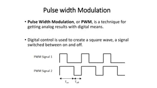
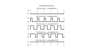
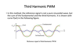
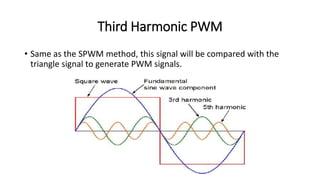
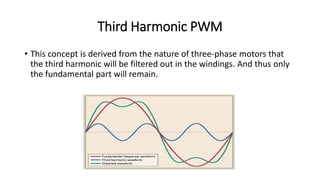
6th Sem
Electrical Engineering Department
Batch – B1 (2014 Batch)
Abhishek Choksi
(140120109005)
Power Electronics 2 (2160902)
ALA Presentation
On
“Third Harmonic PWM”
Prepared By: Guided By:
Prof. Jaydeep Vanapariya
Gandhinagar Institute Of Technology
Pulse width Modulation
• Pulse Width Modulation, or PWM, is a technique for
getting analog results with digital means.
• Digital control is used to create a square wave, a signal
switched between on and off.
Third Harmonic PWM
• In this method, the reference signal is not a pure sinusoidal wave, but
the sum of the fundamental and the third harmonic. It is shown with
curve f(wt) in the following figure.
Third Harmonic PWM
• Same as the SPWM method, this signal will be compared with the
triangle signal to generate PWM signals.
Third Harmonic PWM
• This concept is derived from the nature of three-phase motors that
the third harmonic will be filtered out in the windings. And thus only
the fundamental part will remain.
References
• Hirak Patangia, Sri Nikhil Gupta Gourisetti, “Real Time Harmonic
Elimination Using a Modified Carrier”, CONIELECOMP, Mexico, Feb
2012.
• Hirak Patangia, Sri Nikhil Gupta Gourisetti, “A Novel Strategy for
Selective Harmonic Elimination Based on a Sine-Sine PWM Model”,
MWSCAS, U.S.A, Aug 2012.
• Wikipedia -- https://en.wikipedia.org/wiki/Pulse-
width_modulation#Principle
Third harmonic pwm

Third harmonic pwm

  • 1.
    6th Sem Electrical EngineeringDepartment Batch – B1 (2014 Batch) Abhishek Choksi (140120109005) Power Electronics 2 (2160902) ALA Presentation On “Third Harmonic PWM” Prepared By: Guided By: Prof. Jaydeep Vanapariya Gandhinagar Institute Of Technology
  • 2.
    Pulse width Modulation •Pulse Width Modulation, or PWM, is a technique for getting analog results with digital means. • Digital control is used to create a square wave, a signal switched between on and off.
  • 4.
    Third Harmonic PWM •In this method, the reference signal is not a pure sinusoidal wave, but the sum of the fundamental and the third harmonic. It is shown with curve f(wt) in the following figure.
  • 5.
    Third Harmonic PWM •Same as the SPWM method, this signal will be compared with the triangle signal to generate PWM signals.
  • 6.
    Third Harmonic PWM •This concept is derived from the nature of three-phase motors that the third harmonic will be filtered out in the windings. And thus only the fundamental part will remain.
  • 7.
    References • Hirak Patangia,Sri Nikhil Gupta Gourisetti, “Real Time Harmonic Elimination Using a Modified Carrier”, CONIELECOMP, Mexico, Feb 2012. • Hirak Patangia, Sri Nikhil Gupta Gourisetti, “A Novel Strategy for Selective Harmonic Elimination Based on a Sine-Sine PWM Model”, MWSCAS, U.S.A, Aug 2012. • Wikipedia -- https://en.wikipedia.org/wiki/Pulse- width_modulation#Principle