Downloaded 457 times


This document discusses phasor analysis of RC, RL, and RLC circuits. For an RC circuit, the voltage across the capacitor lags behind the current by 90 degrees. For an RL circuit, the voltage across the inductor leads the current by 90 degrees. For an RLC circuit, the behavior depends on whether the reactance of the inductor or capacitor is higher. If the inductor reactance is higher, it behaves like an RL circuit. If the capacitor reactance is higher, it behaves like an RC circuit. If the reactances are equal, it behaves like a resistive circuit.
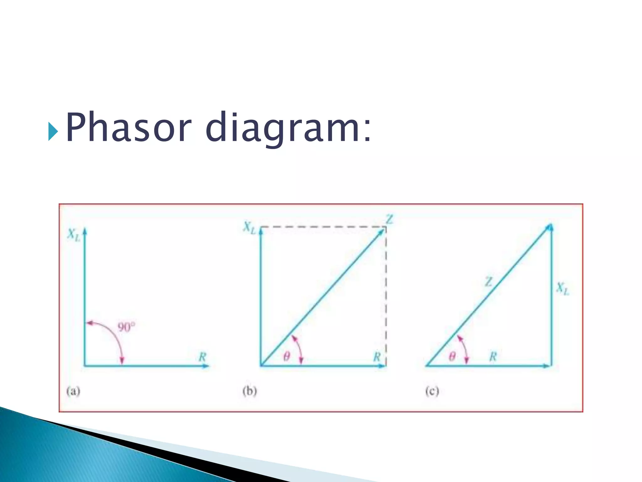
Introduction to phasor diagrams in the context of electrical engineering, specifically R-C circuits.
List of students with their respective enrollment numbers as part of the presentation.
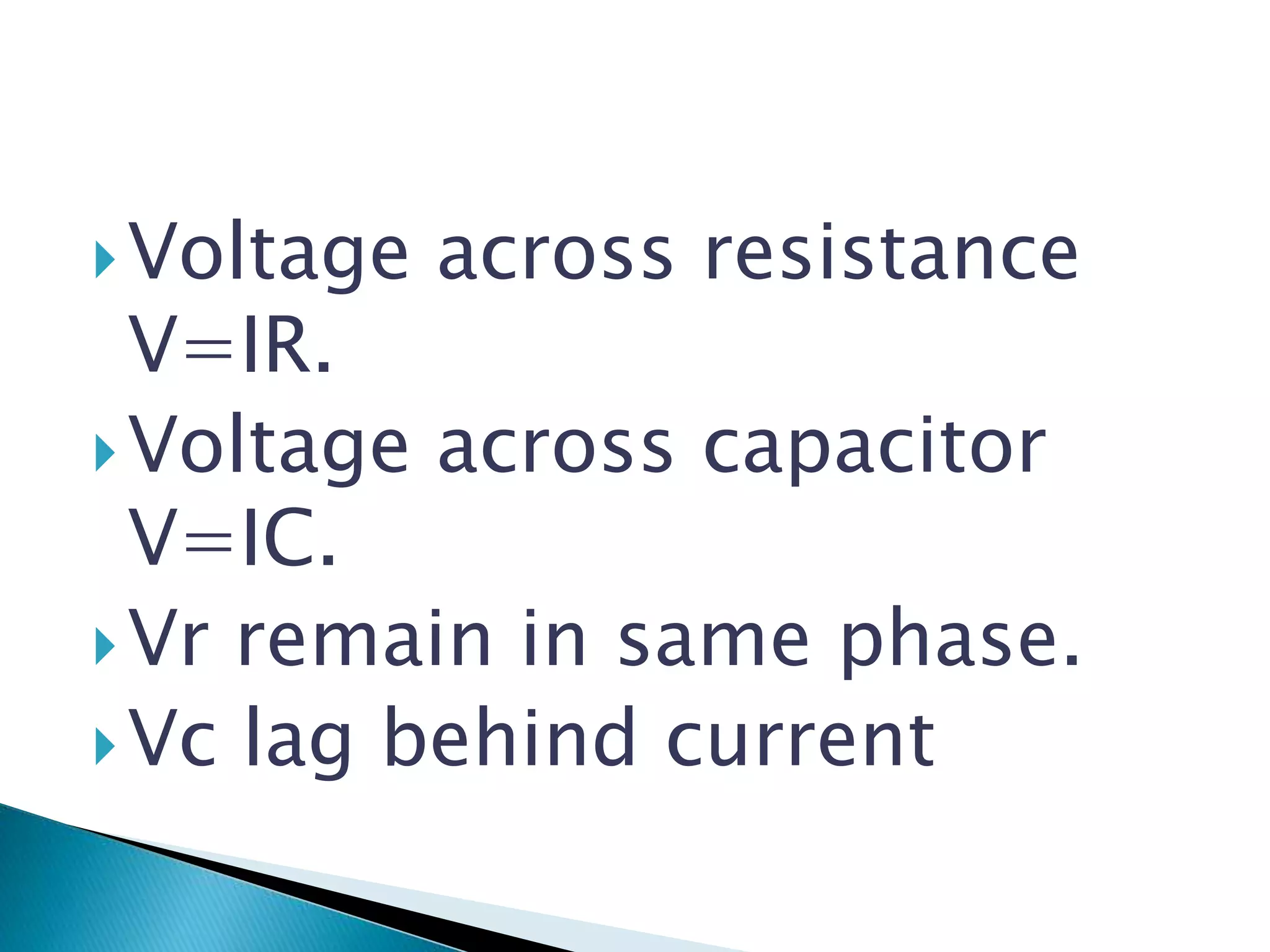
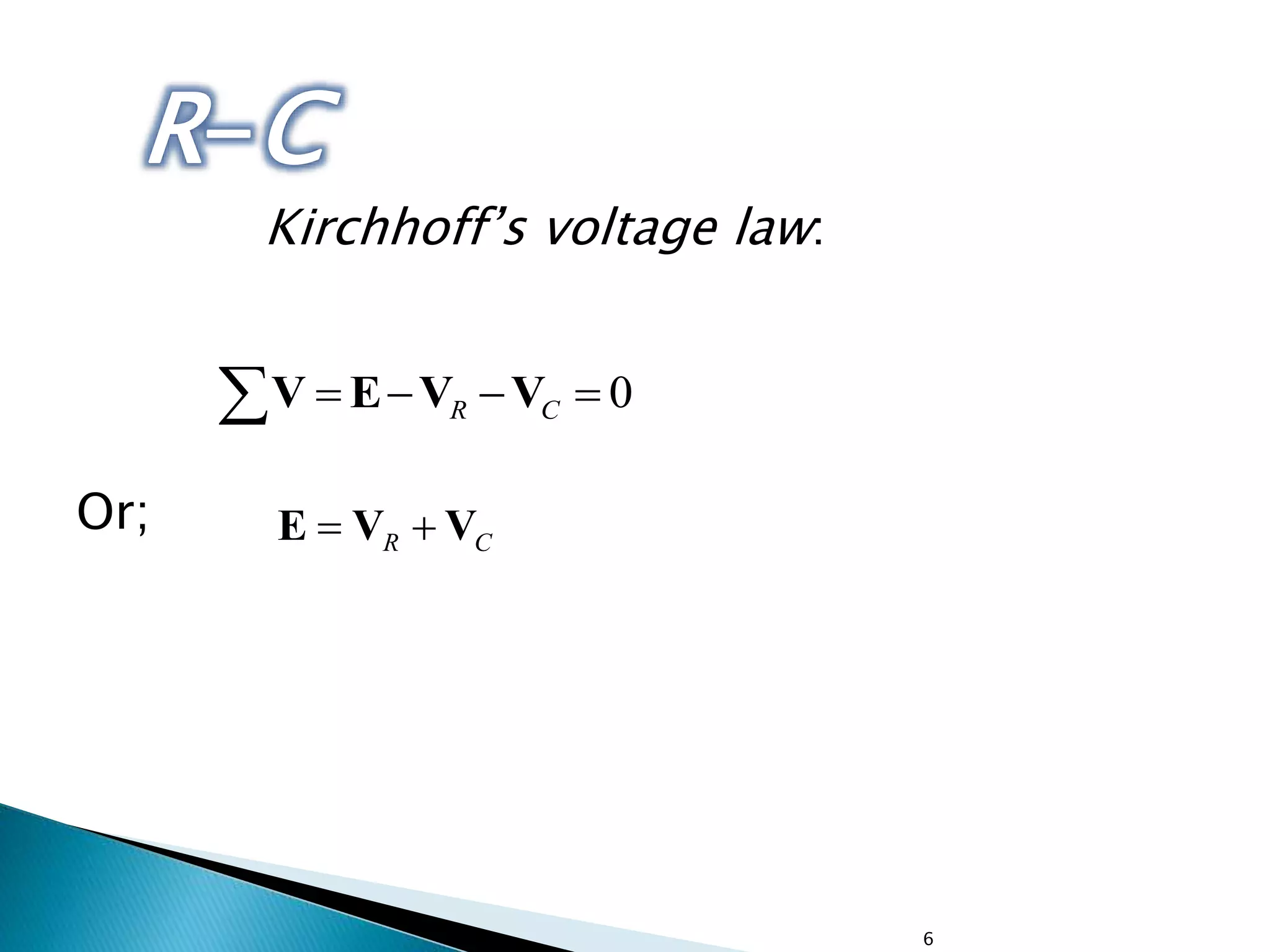
Description of an R-C circuit, voltage relationships in elements, and Kirchhoff’s voltage law.
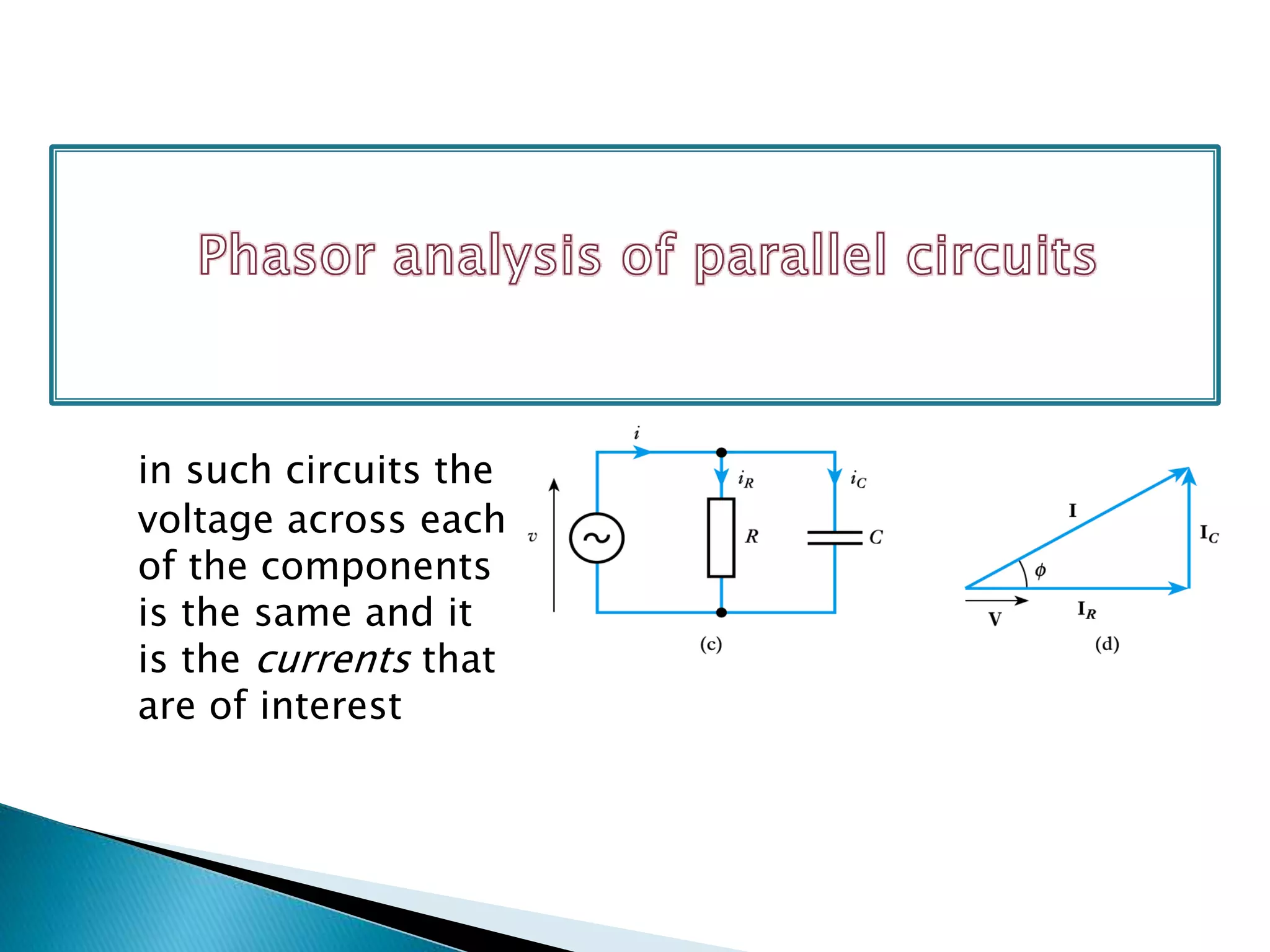
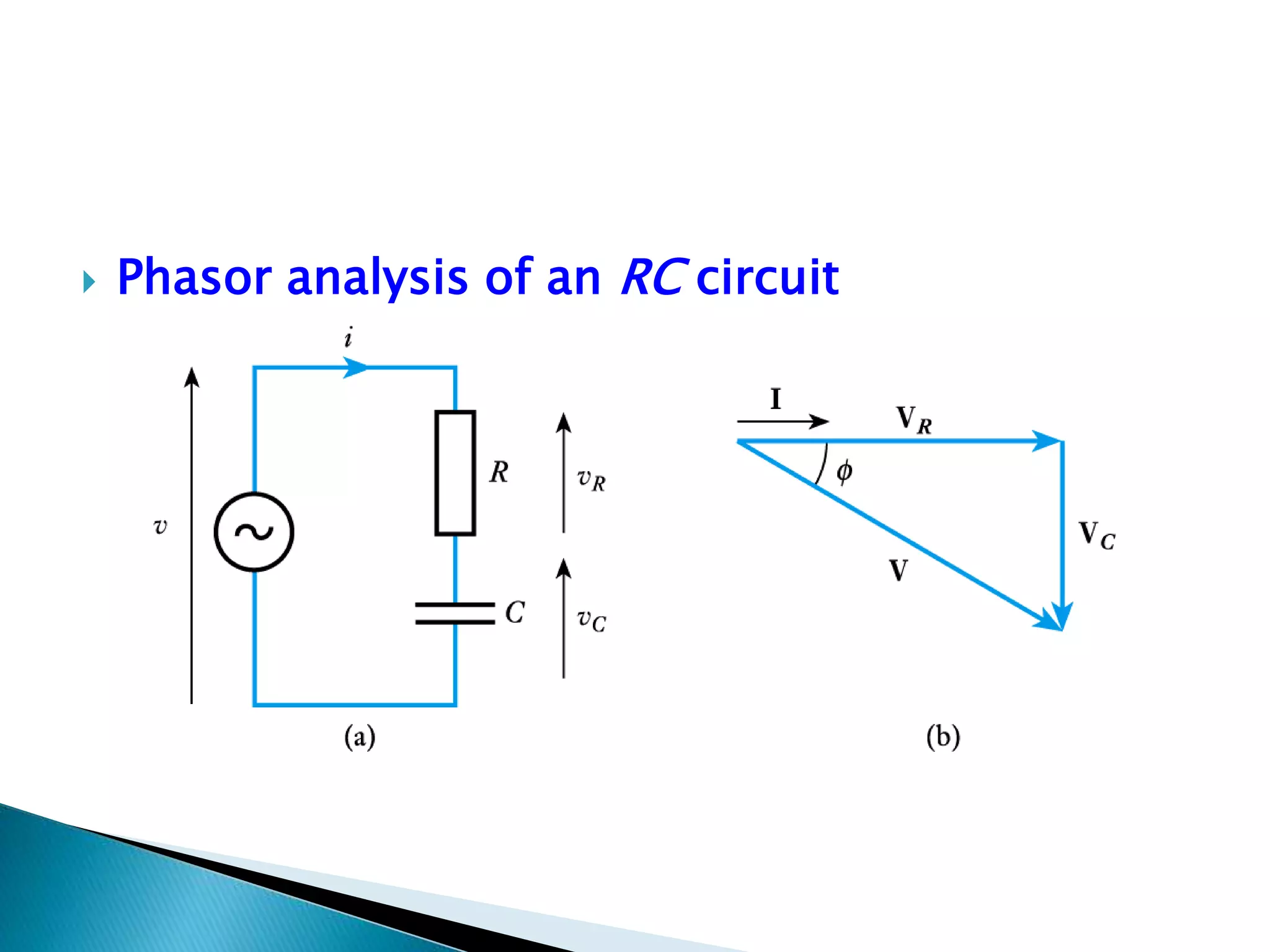
Focus on phasor analysis of the R-C circuit.
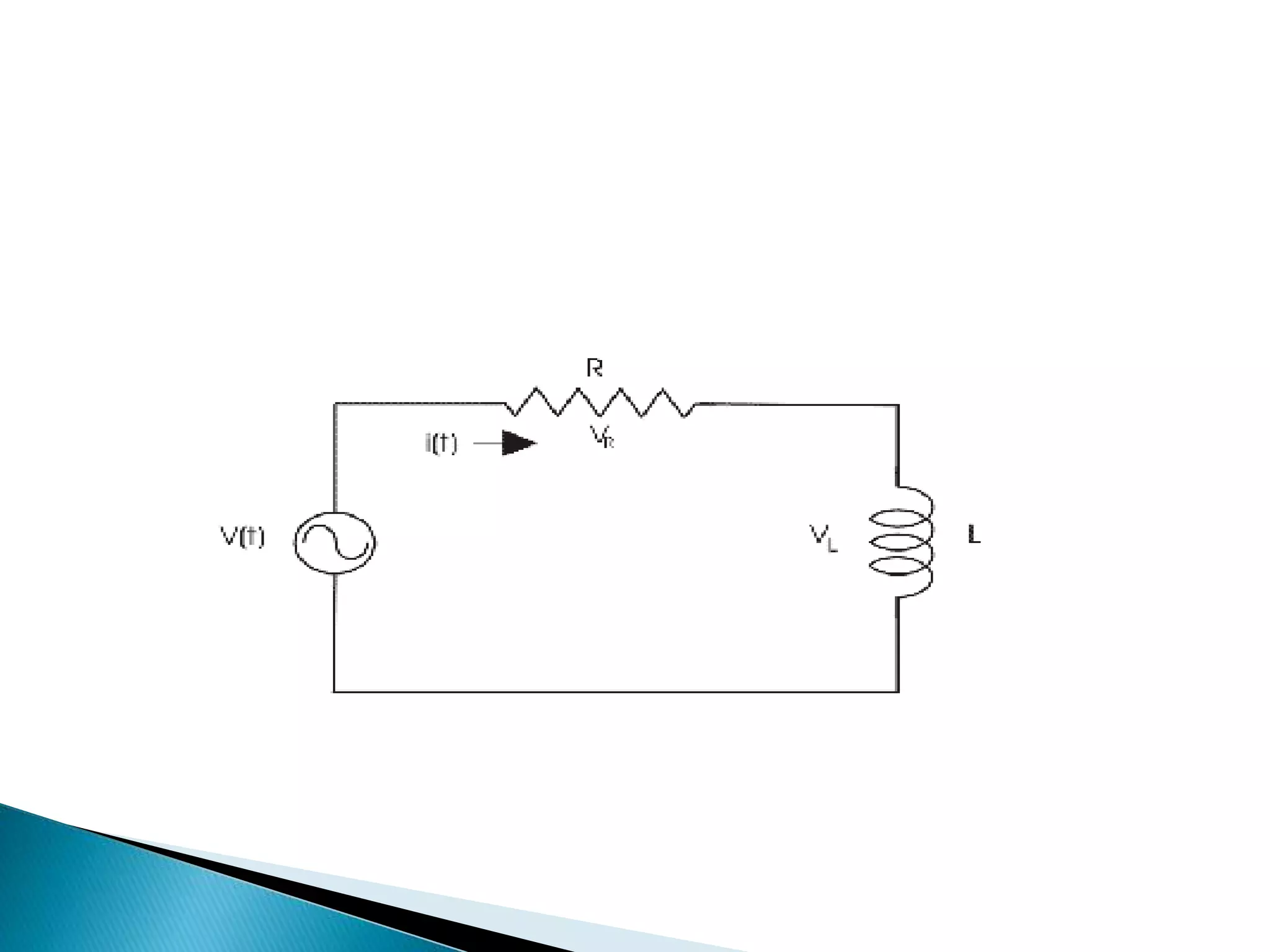
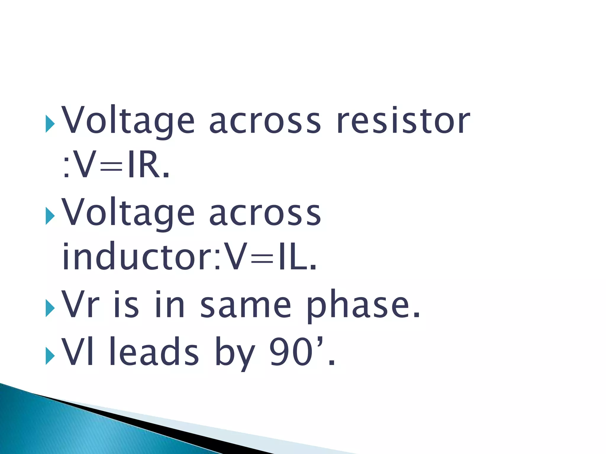
Description of an R-L circuit and the introduction to phasor analysis.
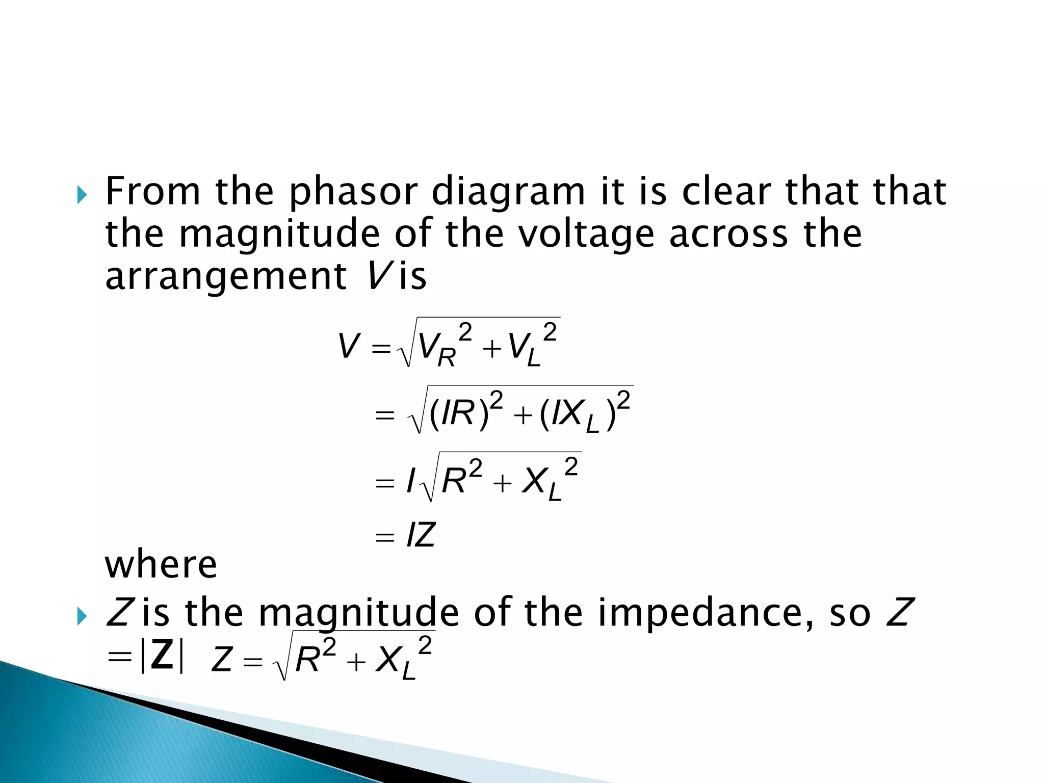
Voltage equations for the resistor and inductor, along with impedance analysis using phasors.
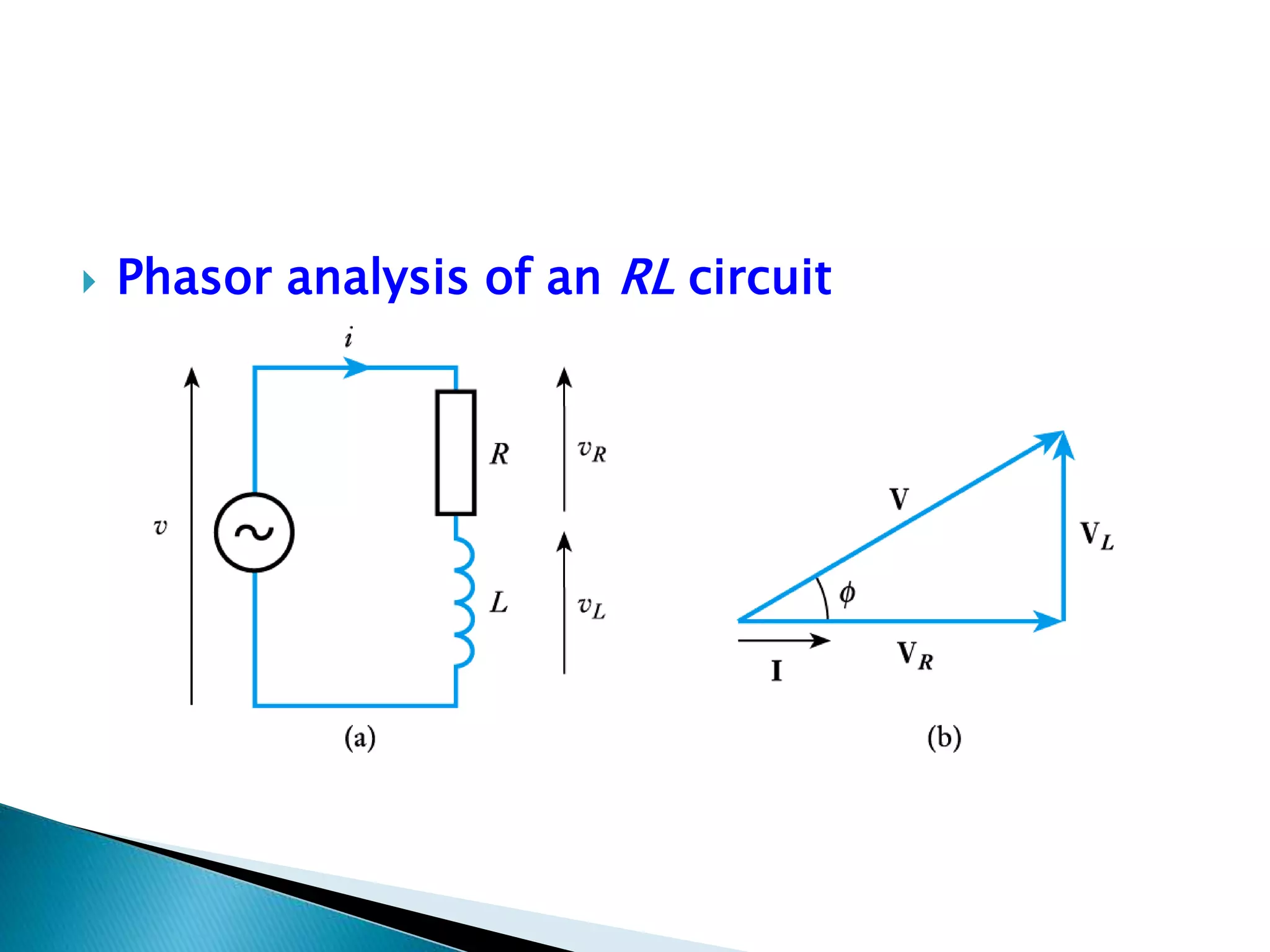
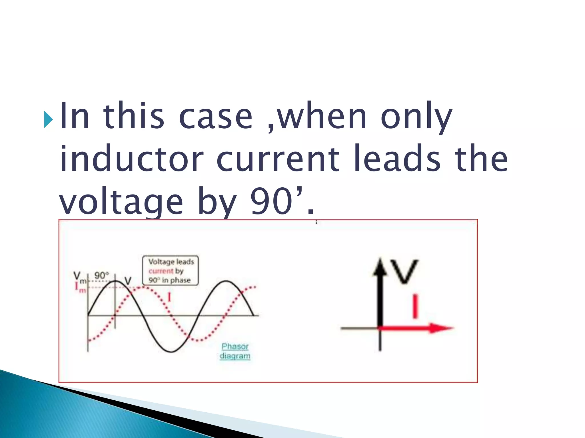
Explains how the inductive current leads voltage by 90 degrees.
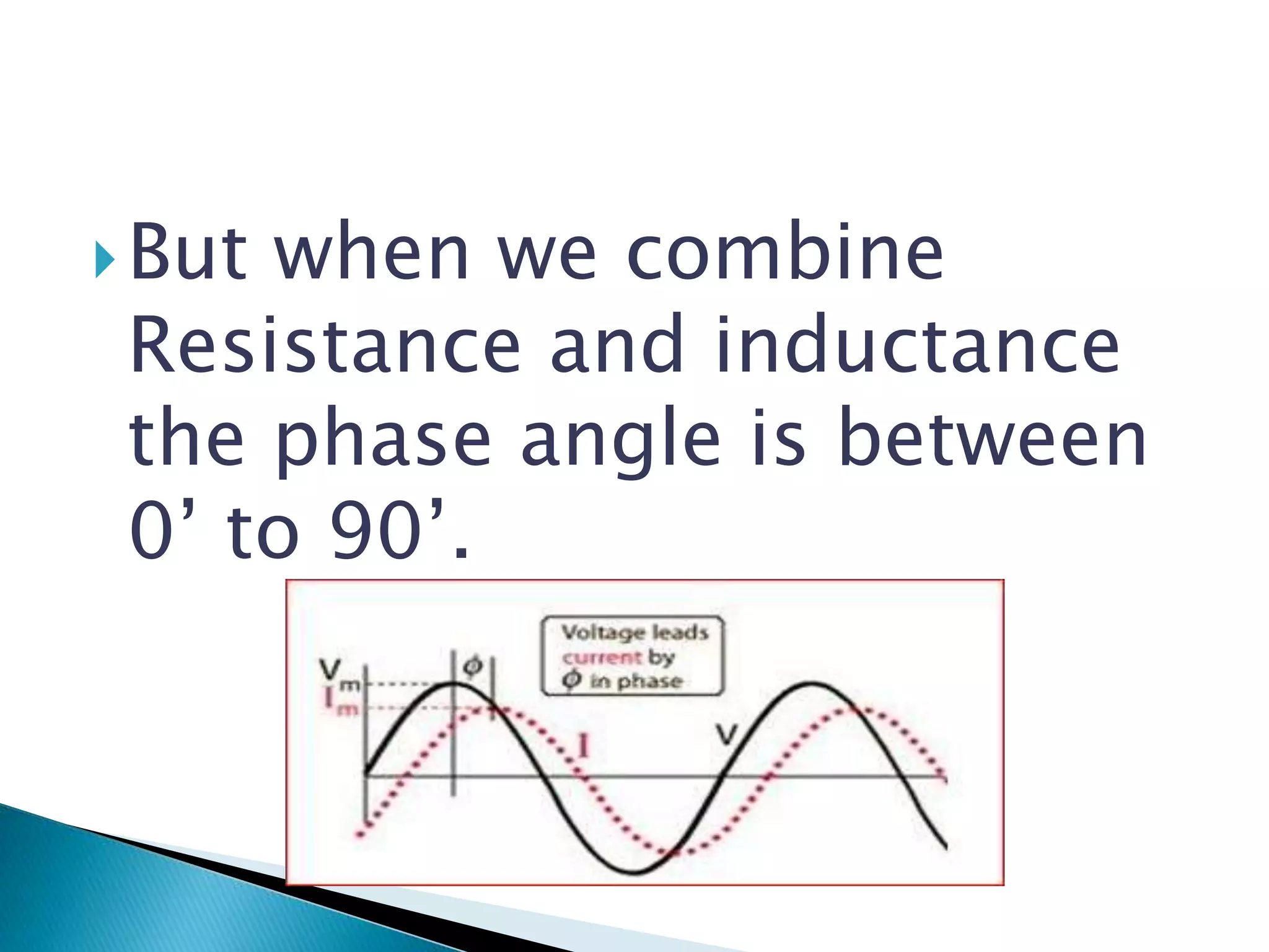
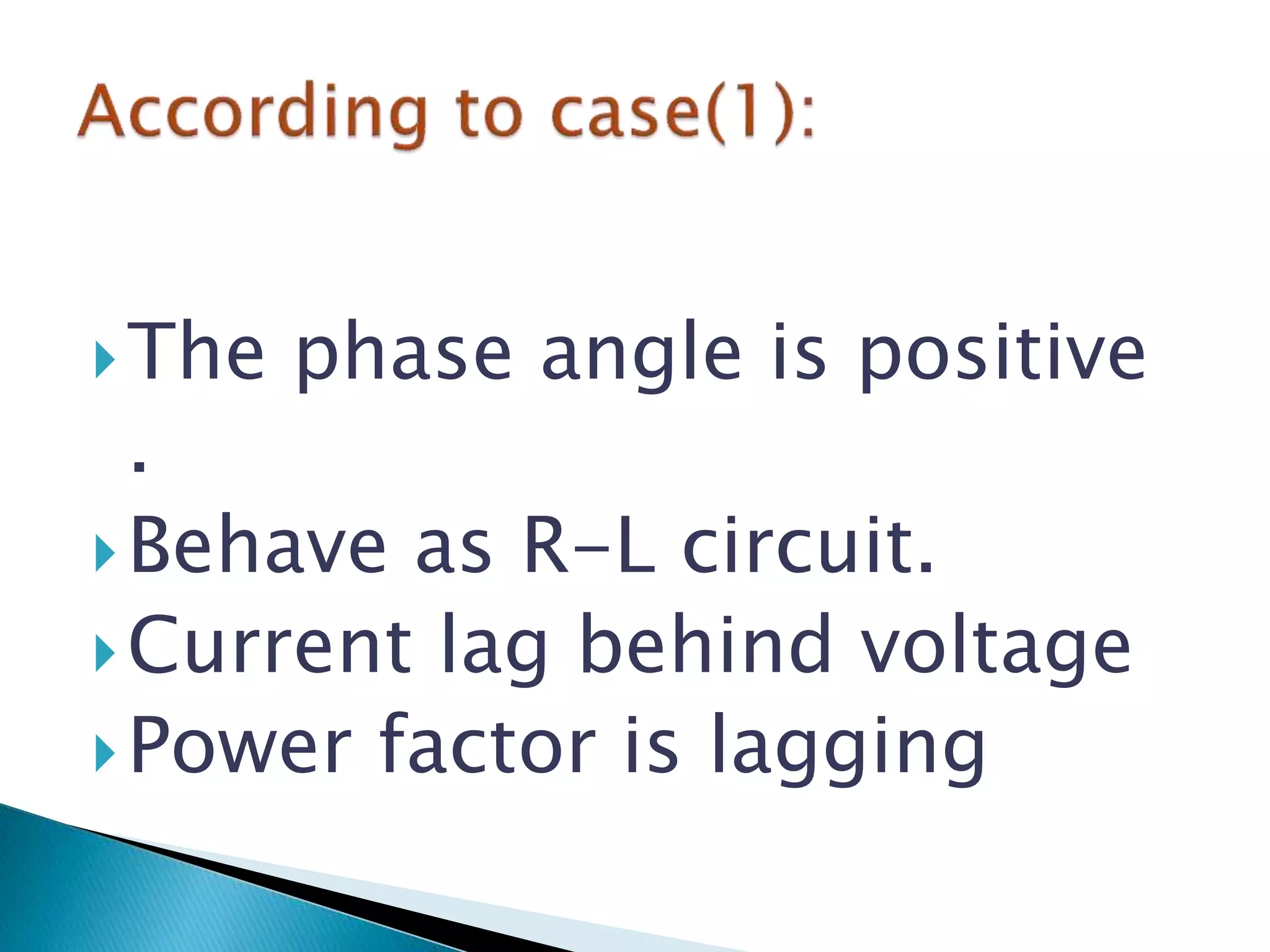
Combining resistance and inductance affects the phase angle between 0 and 90 degrees.
Illustration of the phasor diagram specific to the R-L circuit.
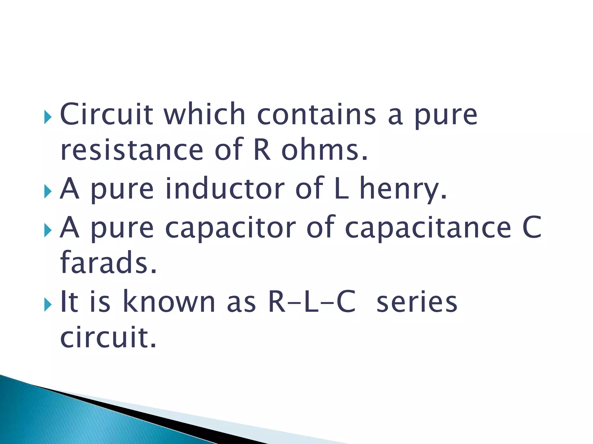
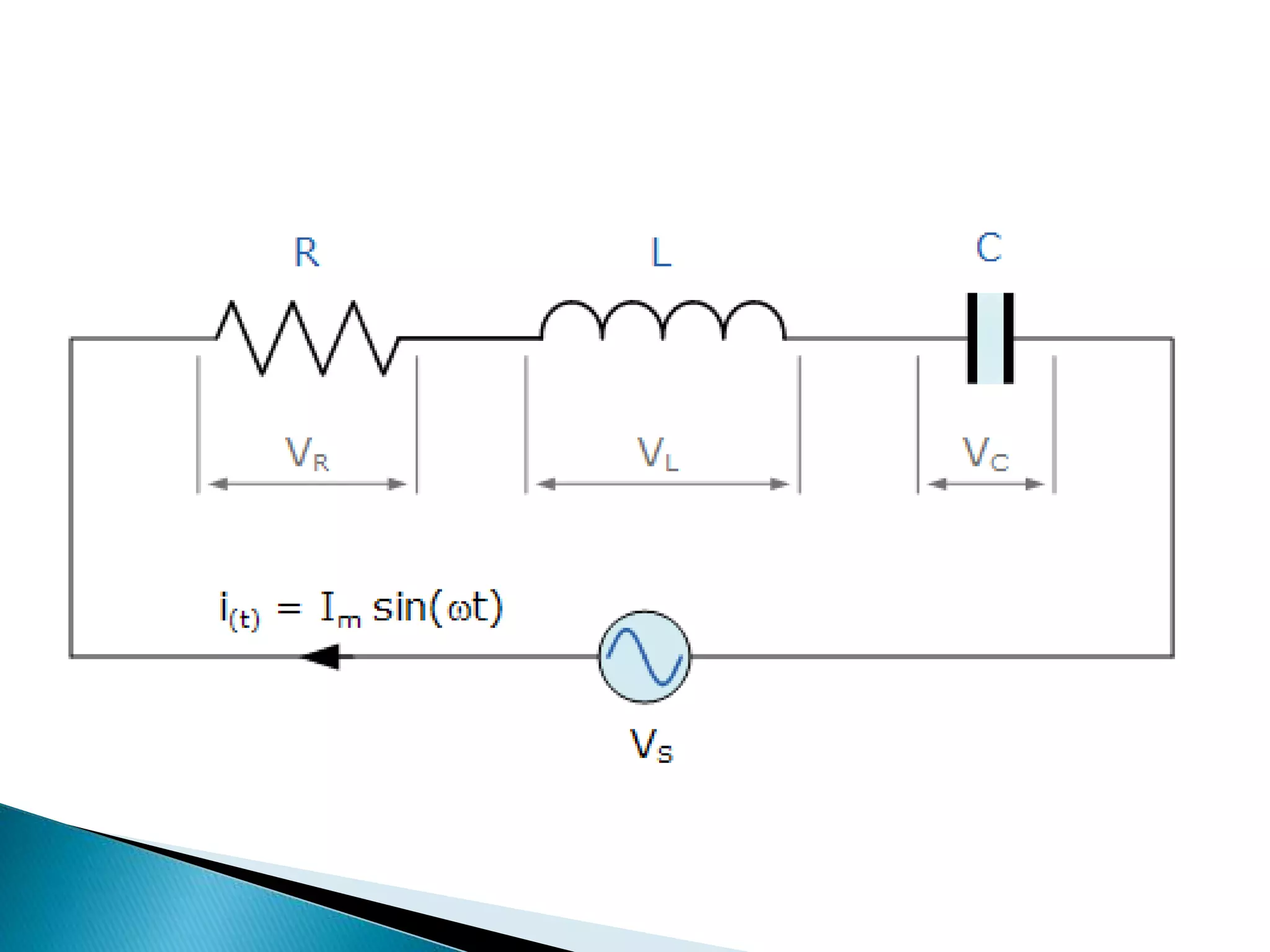
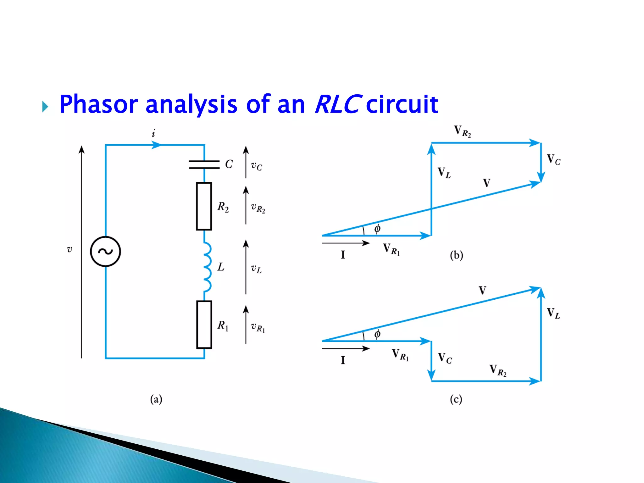
Description of an R-L-C series circuit consisting of a resistor, inductor, and capacitor.
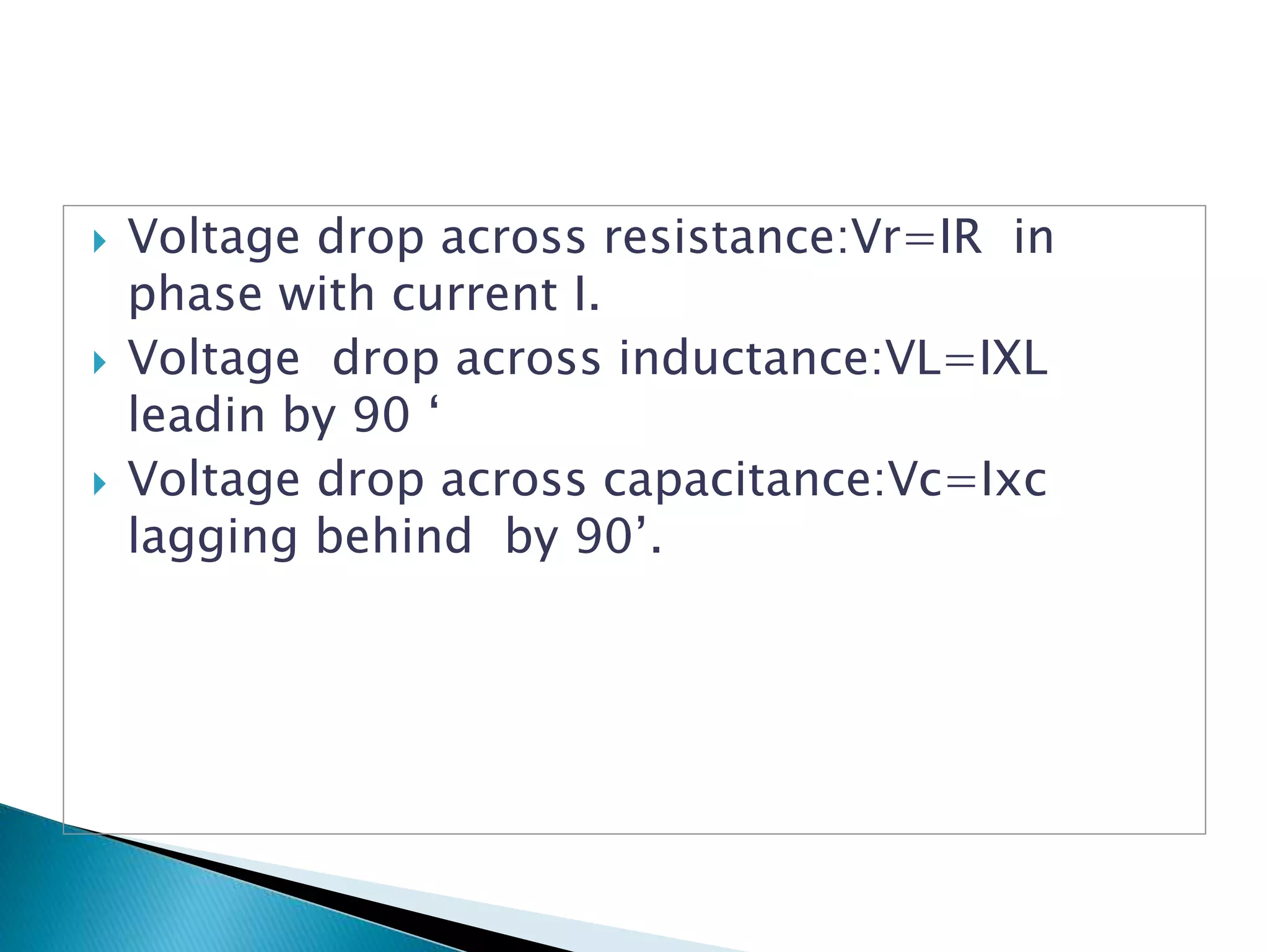
Explanation of voltage drops across resistance, inductance, and capacitance in an R-L-C circuit.
Focus on phasor analysis for understanding the R-L-C circuit behavior.
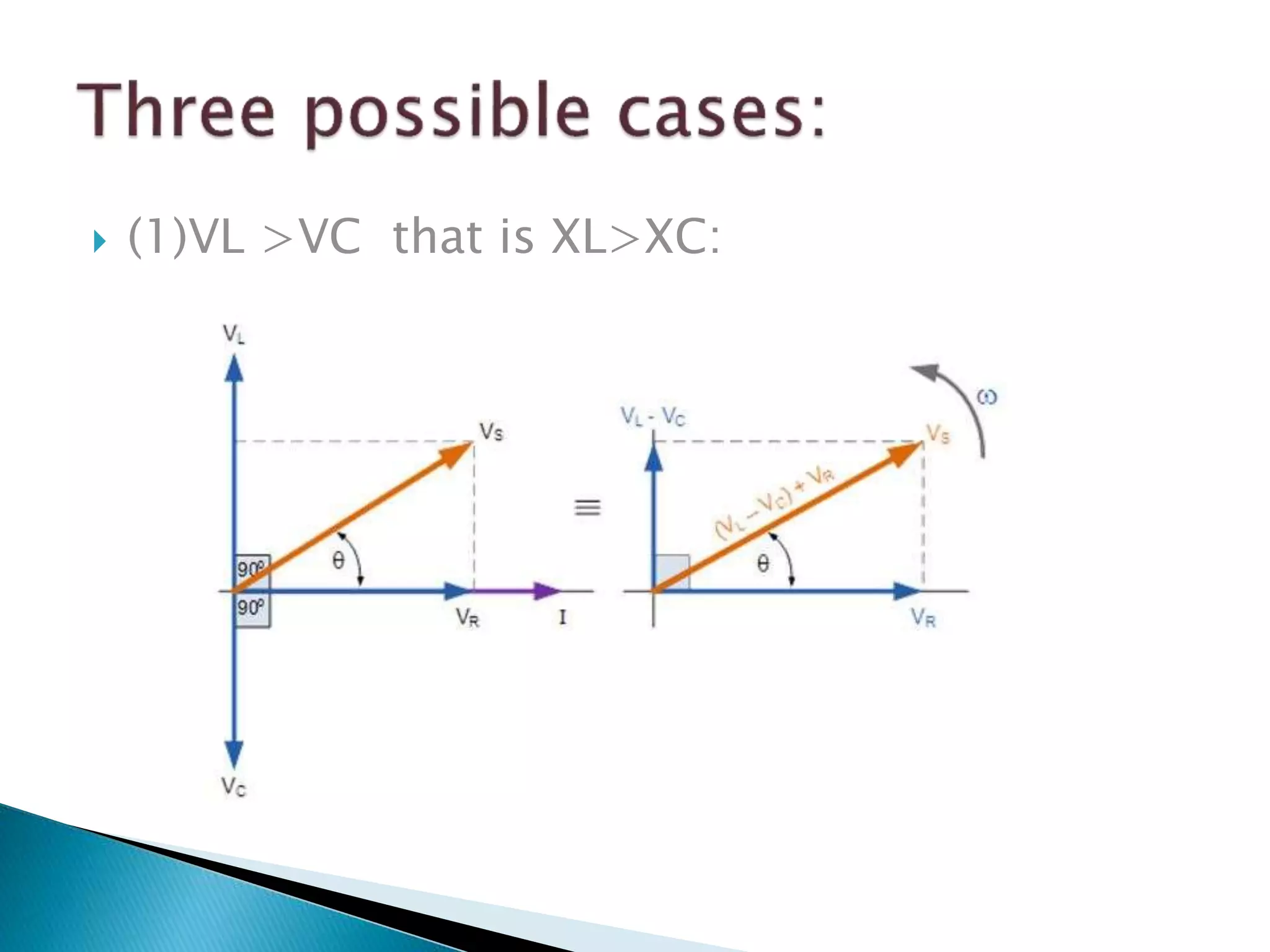
Discussion on voltage relationships with capacitor and inductor leading or lagging.
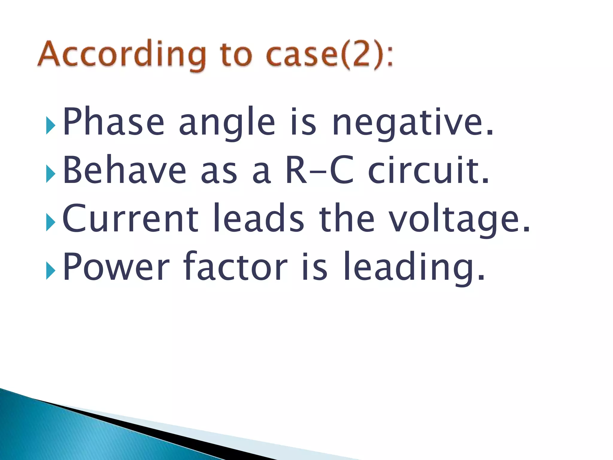
Describes different phase angles (positive, negative, zero) in R-L, R-C, and resistive circuits.