Downloaded 107 times

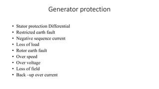


The presentation covers generator protection within electrical engineering, focusing on the necessity of protective systems to isolate faulty equipment in generating stations. It elaborates on various protective schemes including stator and rotor protection techniques, such as differential protection, earth fault protection, and overvoltage protection, alongside their operational principles. The conclusion emphasizes that while protective relays cannot prevent faults, they are essential for detecting faults and ensuring safety and equipment protection.


![protection of transmission lines[distance relay protection scheme]](https://cdn.slidesharecdn.com/ss_thumbnails/os-exe3-23-may2011-sr-i-776s21tr-lineprotection-120425095503-phpapp02-thumbnail.jpg?width=640&height=640&fit=bounds)


