Downloaded 26 times


The document presents a presentation on the design of magnetic circuits for AC machines, focusing on the calculation of magnetomotive force (MMF) for various components including airgap, armature teeth, core, poles, and yoke. It elaborates on the principles of calculating MMF using flux densities and geometric relationships, emphasizing the variability of flux within poles. References include Wikipedia and a textbook on electrical machine design by A.K. Sawhney.
Presentation on the design of magnetic circuits in AC machines, specifically by Abhishek Choksi under guidance of Prof. Purv Mistry.
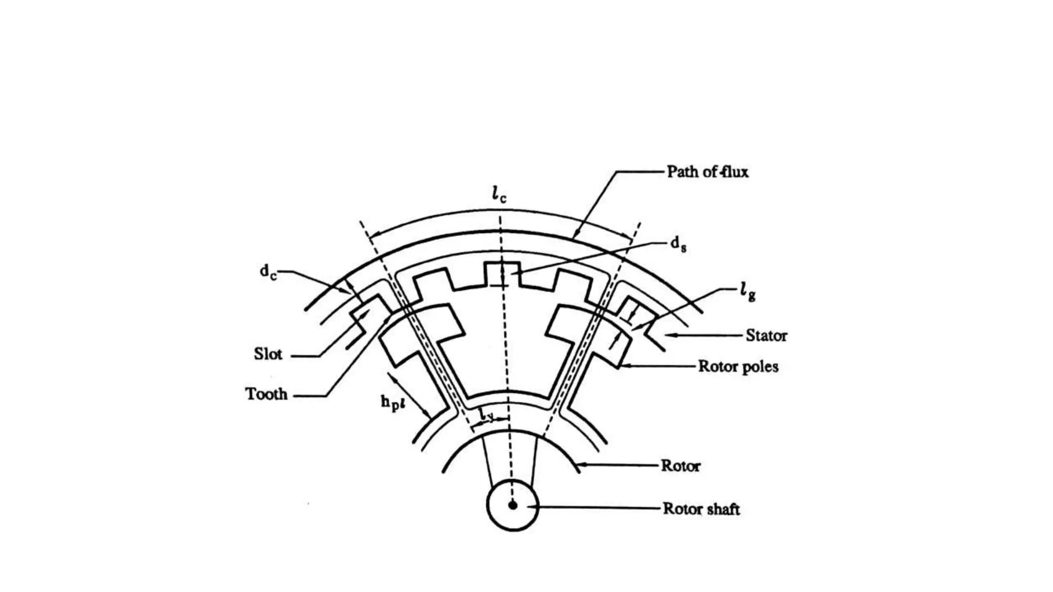
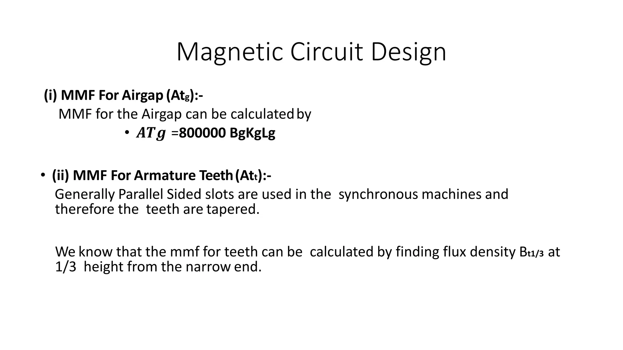
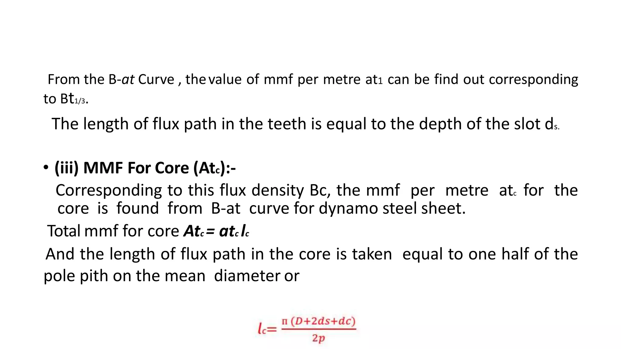
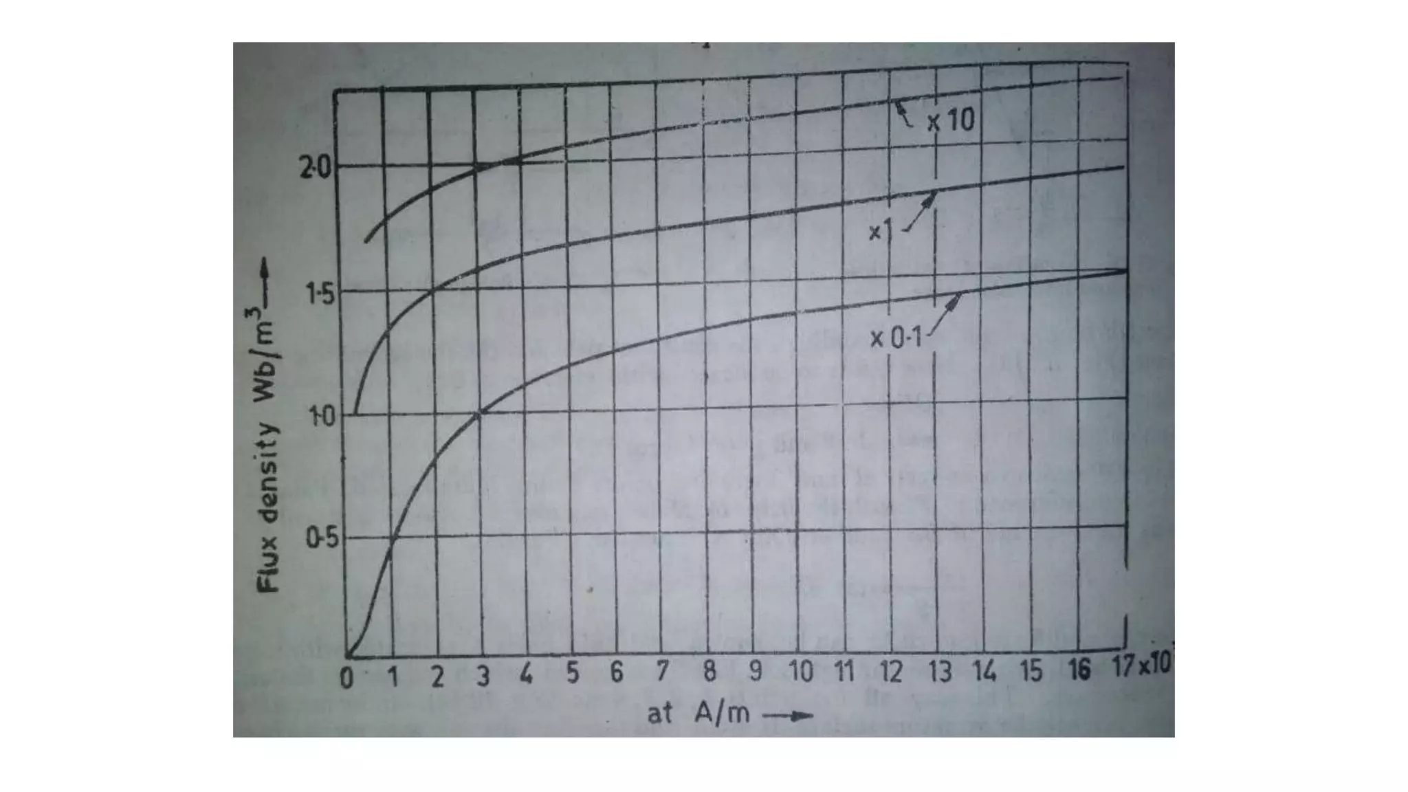
Discusses MMF calculations for various components: Airgap (Atg), Armature Teeth (Att), and Core (Atc) using B-at curves.
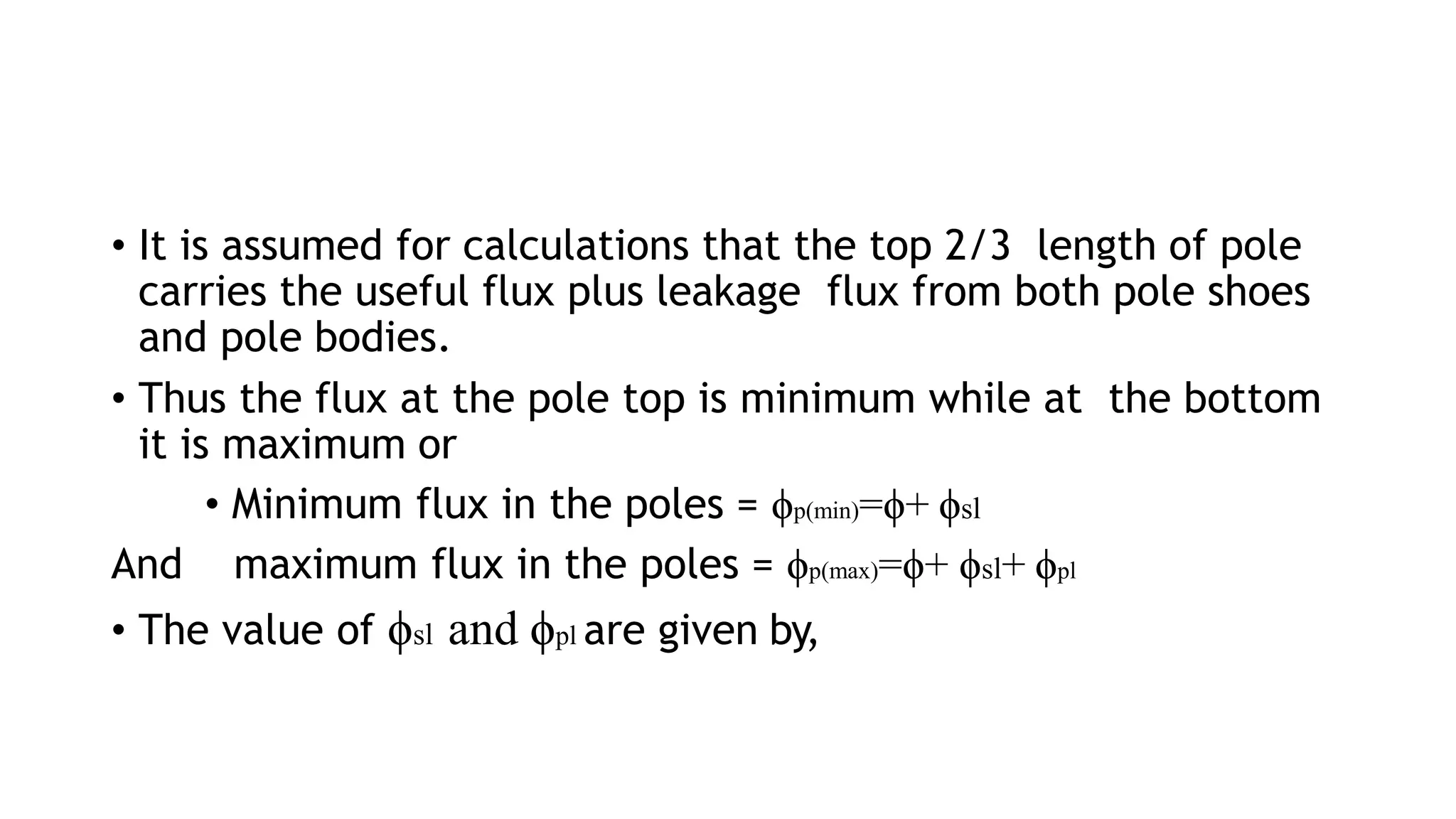
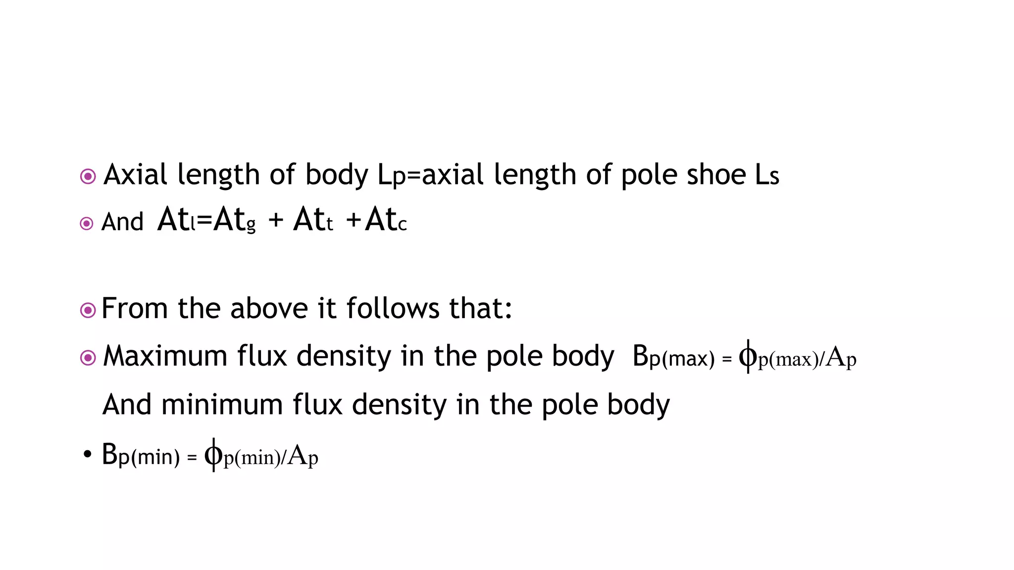
MMF for poles (Atp) considers useful and leakage flux, calculating minimum and maximum flux, and corresponding MMF values.
Calculates MMF for the yoke (Aty), considering yoke area and flux density, along with total field MMF required at no load.
Cites references including Wikipedia and a textbook by A.K. Sawhney for further reading in electrical machine design.


