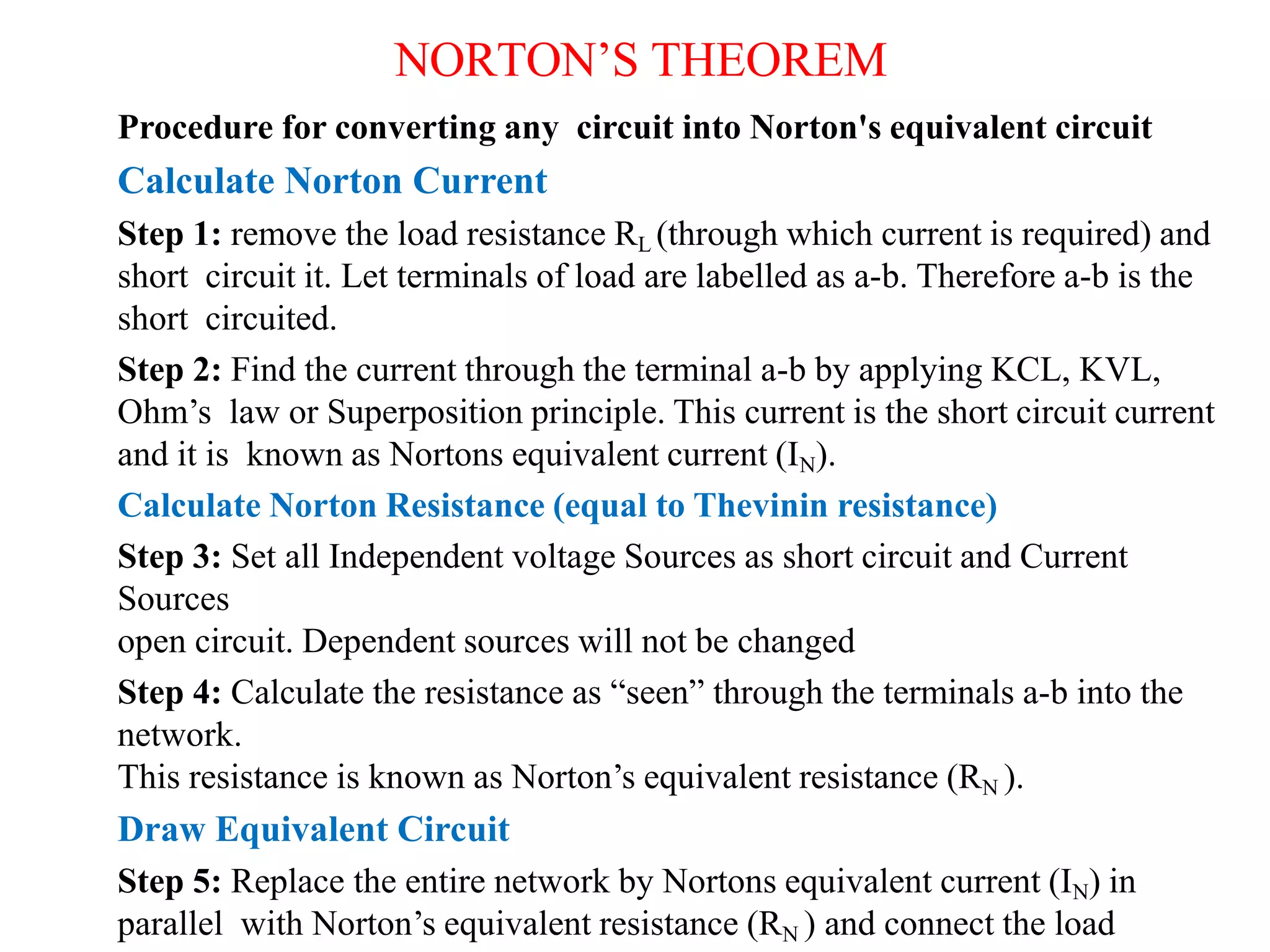
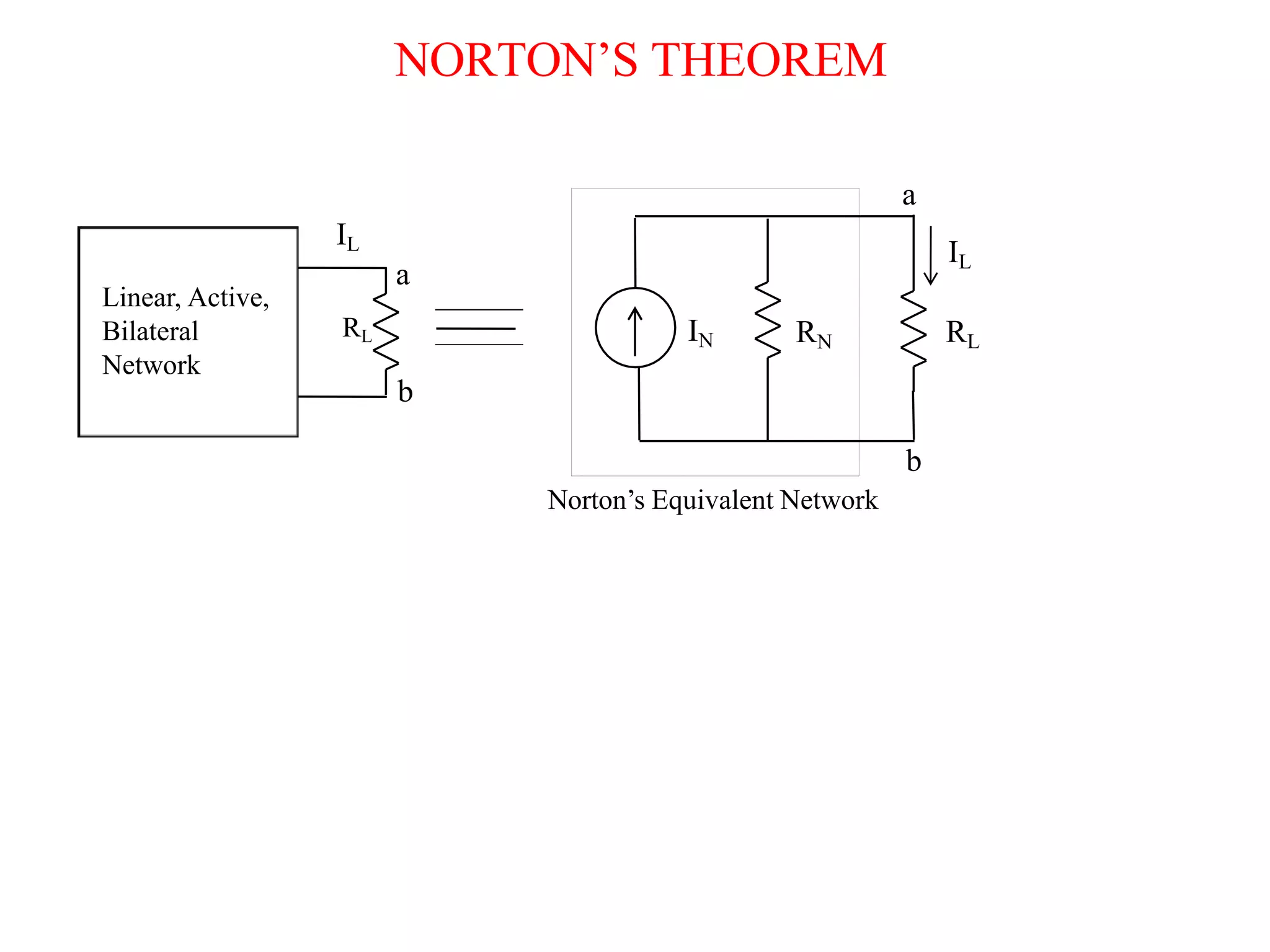
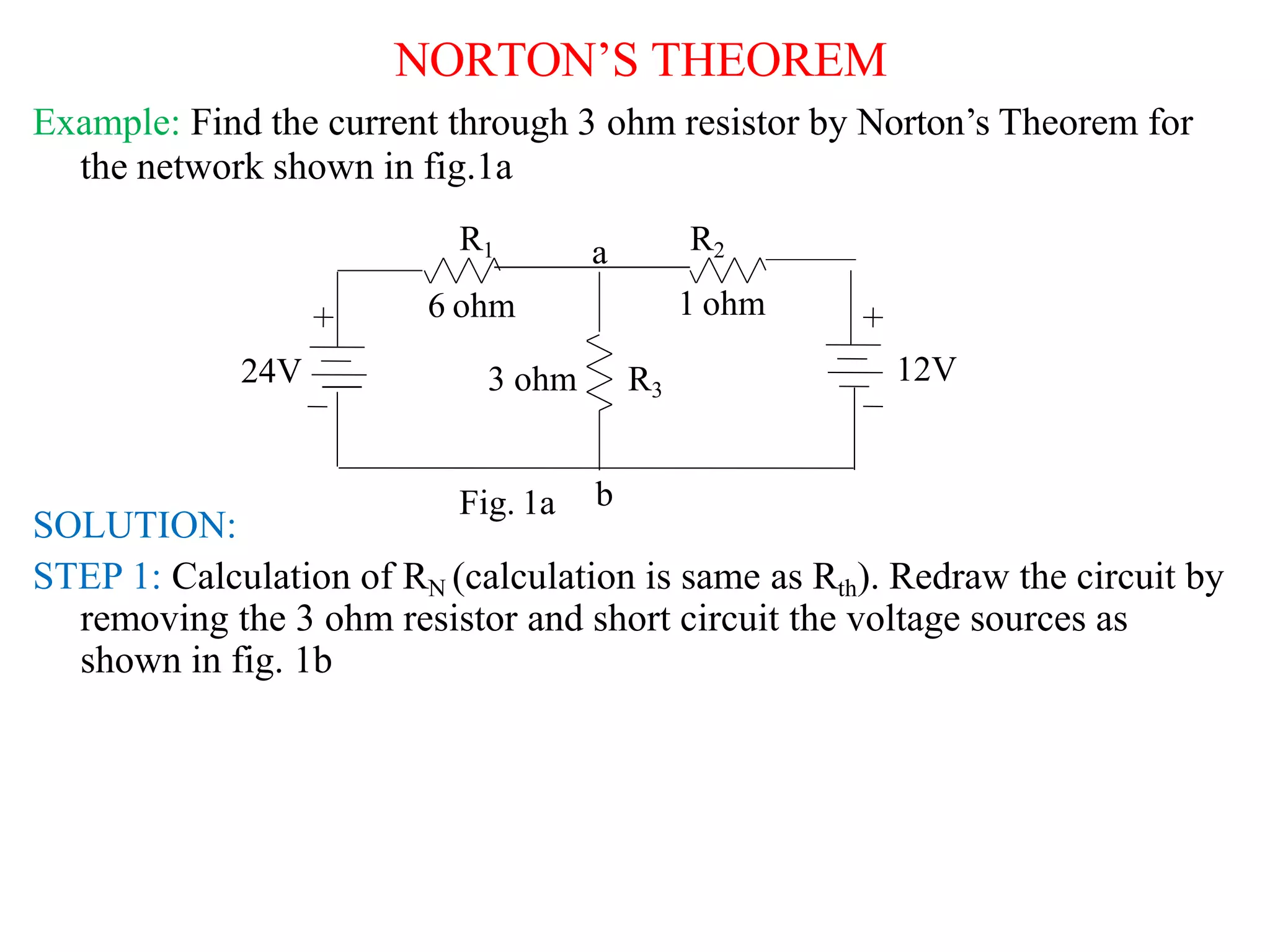
NORTON’S THEOREM
PRESENTED BY:
NAME:P.SNEHA
BRANCH:ECE-A
ROLL NO:22R21A0446
NORTON’S THEOREM
STATEMENT: Any linear, active, bilateral dc network having a number of
voltage sources and/or current sources with resistances can be replaced by
a simple equivalent circuit having single current source (IN) in parallel
with a single resistance (RN).
Where (IN) is the known as Norton’s equivalent current through the terminal
a-b.
(RN) is the Norton’s equivalent resistance viewed back into the network from
terminal a-b.
Note: independent voltage sources are short circuited and independent
current sources are open circuited. Dependent sources will remain in the
circuit for the calculation of Norton’s equivalent resistance.
NORTON’S THEOREM
Procedure for converting any circuit into Norton's equivalent circuit
Calculate Norton Current
Step 1: remove the load resistance RL (through which current is required) and
short circuit it. Let terminals of load are labelled as a-b. Therefore a-b is the
short circuited.
Step 2: Find the current through the terminal a-b by applying KCL, KVL,
Ohm’s law or Superposition principle. This current is the short circuit current
and it is known as Nortons equivalent current (IN).
Calculate Norton Resistance (equal to Thevinin resistance)
Step 3: Set all Independent voltage Sources as short circuit and Current
Sources
open circuit. Dependent sources will not be changed
Step 4: Calculate the resistance as “seen” through the terminals a-b into the
network.
This resistance is known as Norton’s equivalent resistance (RN ).
Draw Equivalent Circuit
Step 5: Replace the entire network by Nortons equivalent current (IN) in
parallel with Norton’s equivalent resistance (RN ) and connect the load
NORTON’S THEOREM
Linear, Active,
Bilateral
Network
RL
a
b
IL
b
Norton’s Equivalent Network
RL
a
IL
RN
IN
NORTON’S THEOREM
Example: Find the current through 3 ohm resistor by Norton’s Theorem for
the network shown in fig.1a
SOLUTION:
STEP 1: Calculation of RN (calculation is same as Rth). Redraw the circuit by
removing the 3 ohm resistor and short circuit the voltage sources as
shown in fig. 1b
Fig. 1a
6 ohm 1 ohm
12V
24V 3 ohm R3
R1 a R2
b
NORTON’S THEOREM
6 ohm 1 ohm
R2
a
b
R2
b
24V 12V
a
IN
R1
RN
Step2: Calculation of
Norton’s Current IN :
Short circuit the
terminals a-b and the
current flow through a-
b is IN
Fig. 1c
Fig. 1b
R1 and R2 are in parallel
6 1
N 1 2
I  I  I 
24

12
16A

61
 0.857
R  R 6 1
R 
R1R2
2
1
N
I1
I2
NORTON’S THEOREM
Step2: Draw the Norton’s Equivalent Circuit:
IN
16A 0.857 ohm
RN
N
I =16A
RN =
0.857
ohm
R3 =
3 Ohm
Step3: Calculation of Current through R3, Reconnect R3 to Norton’s
Equivalent Circuit (Fig. 1e)
Apply Current divider rule
 3.55A
0.857  3
0.857
L
I 16
IL
R
RN  RL
IL  IN
N
THANK YOU

nortons theorem.ppt

  • 1.
  • 2.
    NORTON’S THEOREM STATEMENT: Anylinear, active, bilateral dc network having a number of voltage sources and/or current sources with resistances can be replaced by a simple equivalent circuit having single current source (IN) in parallel with a single resistance (RN). Where (IN) is the known as Norton’s equivalent current through the terminal a-b. (RN) is the Norton’s equivalent resistance viewed back into the network from terminal a-b. Note: independent voltage sources are short circuited and independent current sources are open circuited. Dependent sources will remain in the circuit for the calculation of Norton’s equivalent resistance.
  • 3.
    NORTON’S THEOREM Procedure forconverting any circuit into Norton's equivalent circuit Calculate Norton Current Step 1: remove the load resistance RL (through which current is required) and short circuit it. Let terminals of load are labelled as a-b. Therefore a-b is the short circuited. Step 2: Find the current through the terminal a-b by applying KCL, KVL, Ohm’s law or Superposition principle. This current is the short circuit current and it is known as Nortons equivalent current (IN). Calculate Norton Resistance (equal to Thevinin resistance) Step 3: Set all Independent voltage Sources as short circuit and Current Sources open circuit. Dependent sources will not be changed Step 4: Calculate the resistance as “seen” through the terminals a-b into the network. This resistance is known as Norton’s equivalent resistance (RN ). Draw Equivalent Circuit Step 5: Replace the entire network by Nortons equivalent current (IN) in parallel with Norton’s equivalent resistance (RN ) and connect the load
  • 4.
  • 5.
    NORTON’S THEOREM Example: Findthe current through 3 ohm resistor by Norton’s Theorem for the network shown in fig.1a SOLUTION: STEP 1: Calculation of RN (calculation is same as Rth). Redraw the circuit by removing the 3 ohm resistor and short circuit the voltage sources as shown in fig. 1b Fig. 1a 6 ohm 1 ohm 12V 24V 3 ohm R3 R1 a R2 b
  • 6.
    NORTON’S THEOREM 6 ohm1 ohm R2 a b R2 b 24V 12V a IN R1 RN Step2: Calculation of Norton’s Current IN : Short circuit the terminals a-b and the current flow through a- b is IN Fig. 1c Fig. 1b R1 and R2 are in parallel 6 1 N 1 2 I  I  I  24  12 16A  61  0.857 R  R 6 1 R  R1R2 2 1 N I1 I2
  • 7.
    NORTON’S THEOREM Step2: Drawthe Norton’s Equivalent Circuit: IN 16A 0.857 ohm RN N I =16A RN = 0.857 ohm R3 = 3 Ohm Step3: Calculation of Current through R3, Reconnect R3 to Norton’s Equivalent Circuit (Fig. 1e) Apply Current divider rule  3.55A 0.857  3 0.857 L I 16 IL R RN  RL IL  IN N
  • 8.