Download to read offline


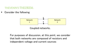
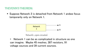
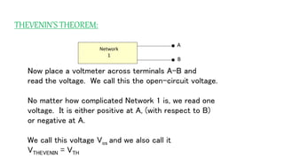
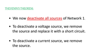
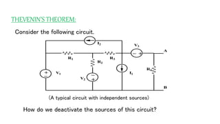
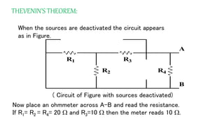
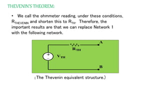
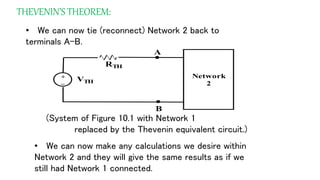
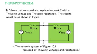
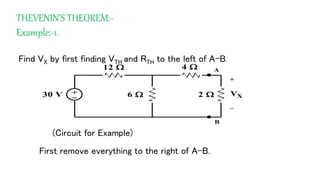
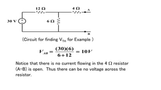
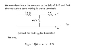
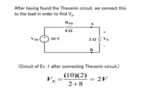
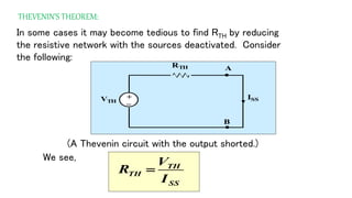
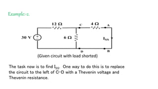
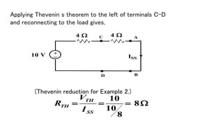


The document discusses Thevenin's theorem, which states that any linear electrical network can be reduced to an equivalent circuit consisting of a voltage source VTH in series with a resistor RTH. It provides examples of finding the Thevenin equivalent circuit for given networks by calculating VTH with open circuits and RTH with deactivated sources. This allows the complex network to be replaced by a simplified model for analysis or connection to other circuits.