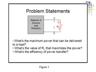
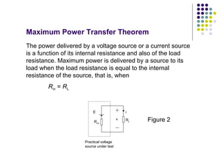
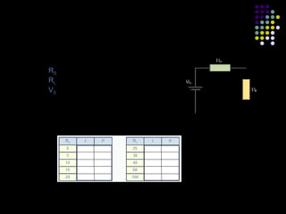
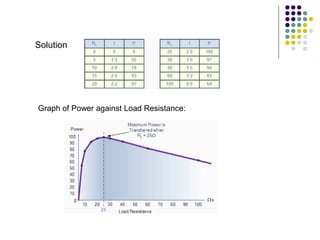
(i) The document discusses the maximum power transfer theorem, which states that maximum power is delivered from a source to its load when the load resistance equals the internal resistance of the source.
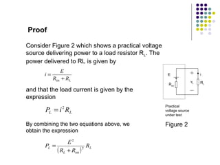
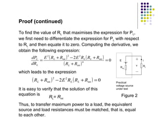
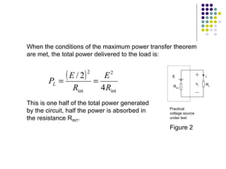
(ii) It provides a proof of this theorem using equations and shows that differentiating the power equation with respect to load resistance and setting it equal to zero results in the load resistance equalling the internal resistance for maximum power transfer.
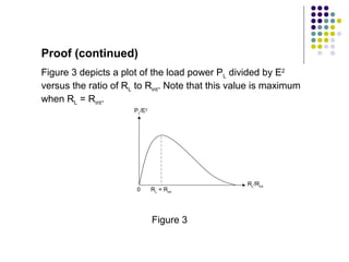
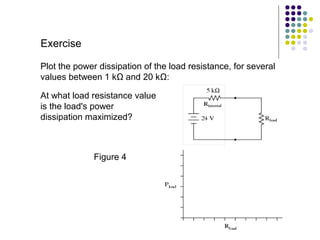
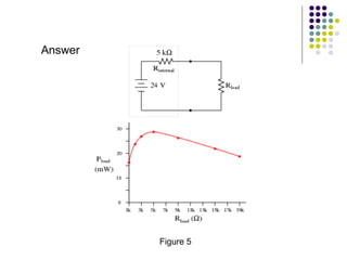
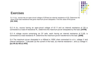
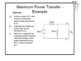
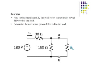
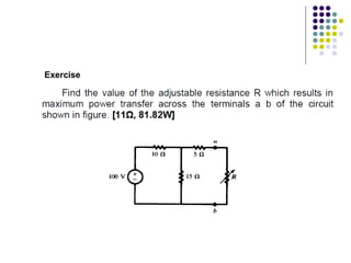
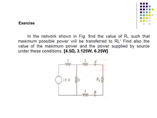
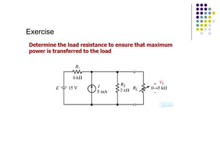
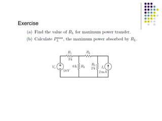
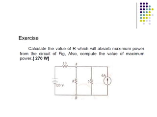
(iii) Examples and exercises are provided to demonstrate applying the maximum power transfer theorem to determine the load resistance that provides maximum power in different circuits.