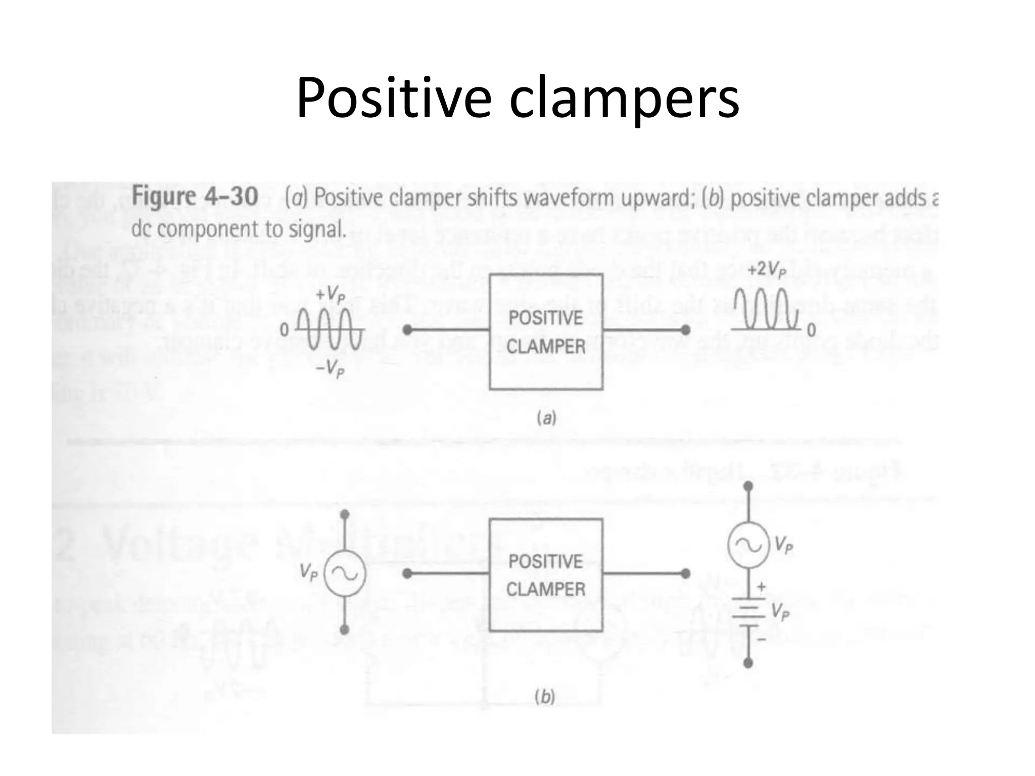
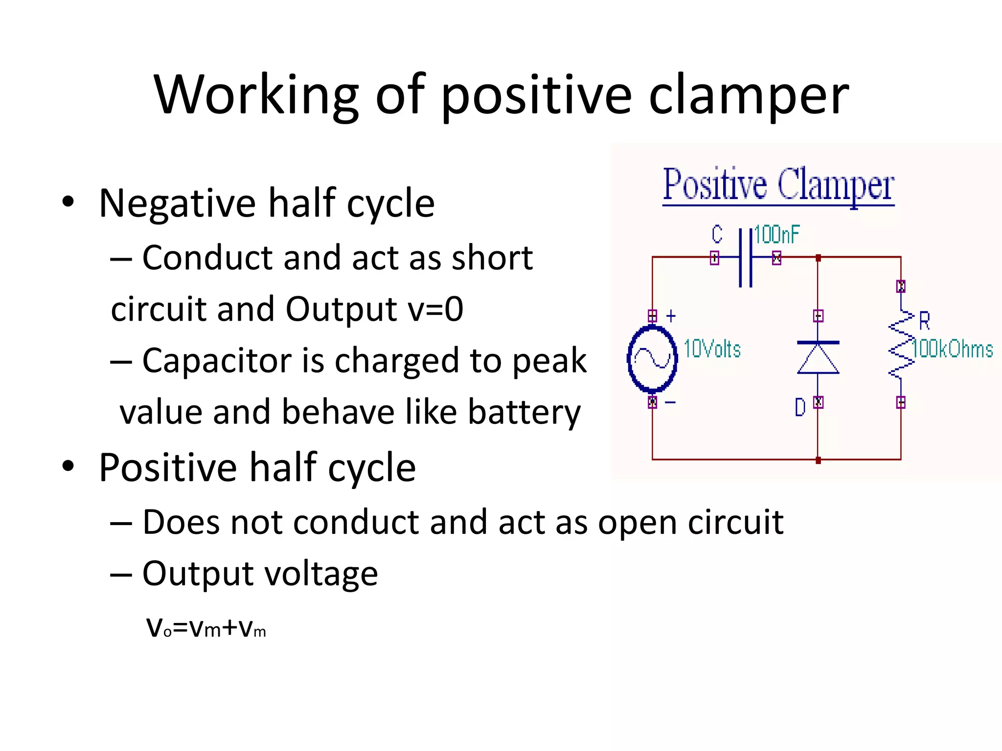
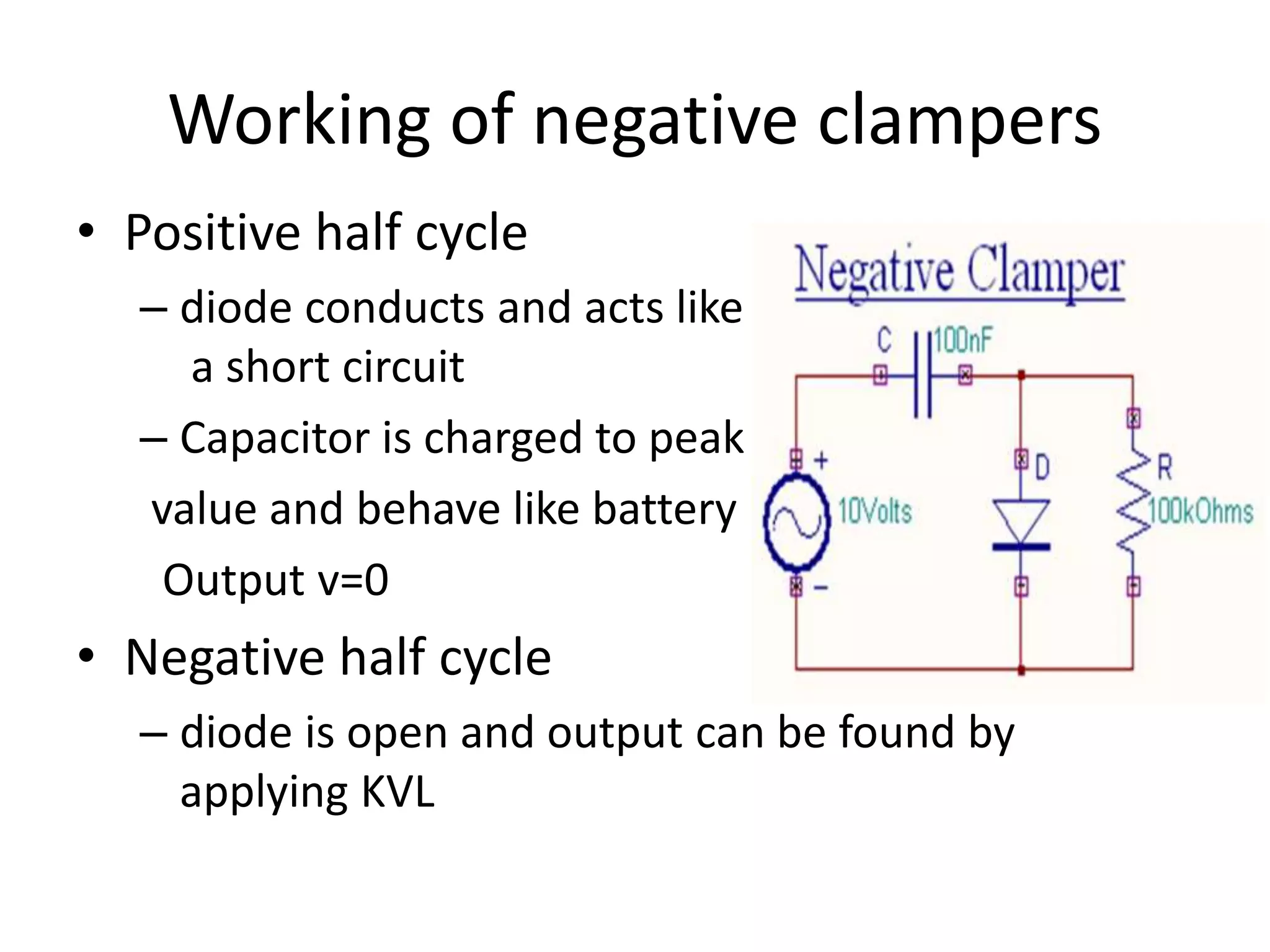
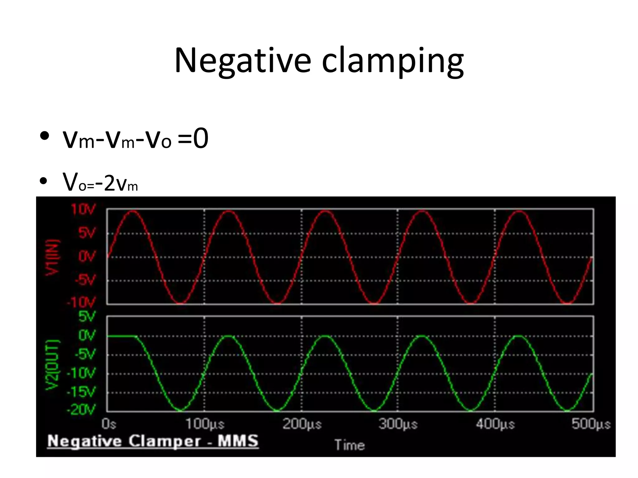
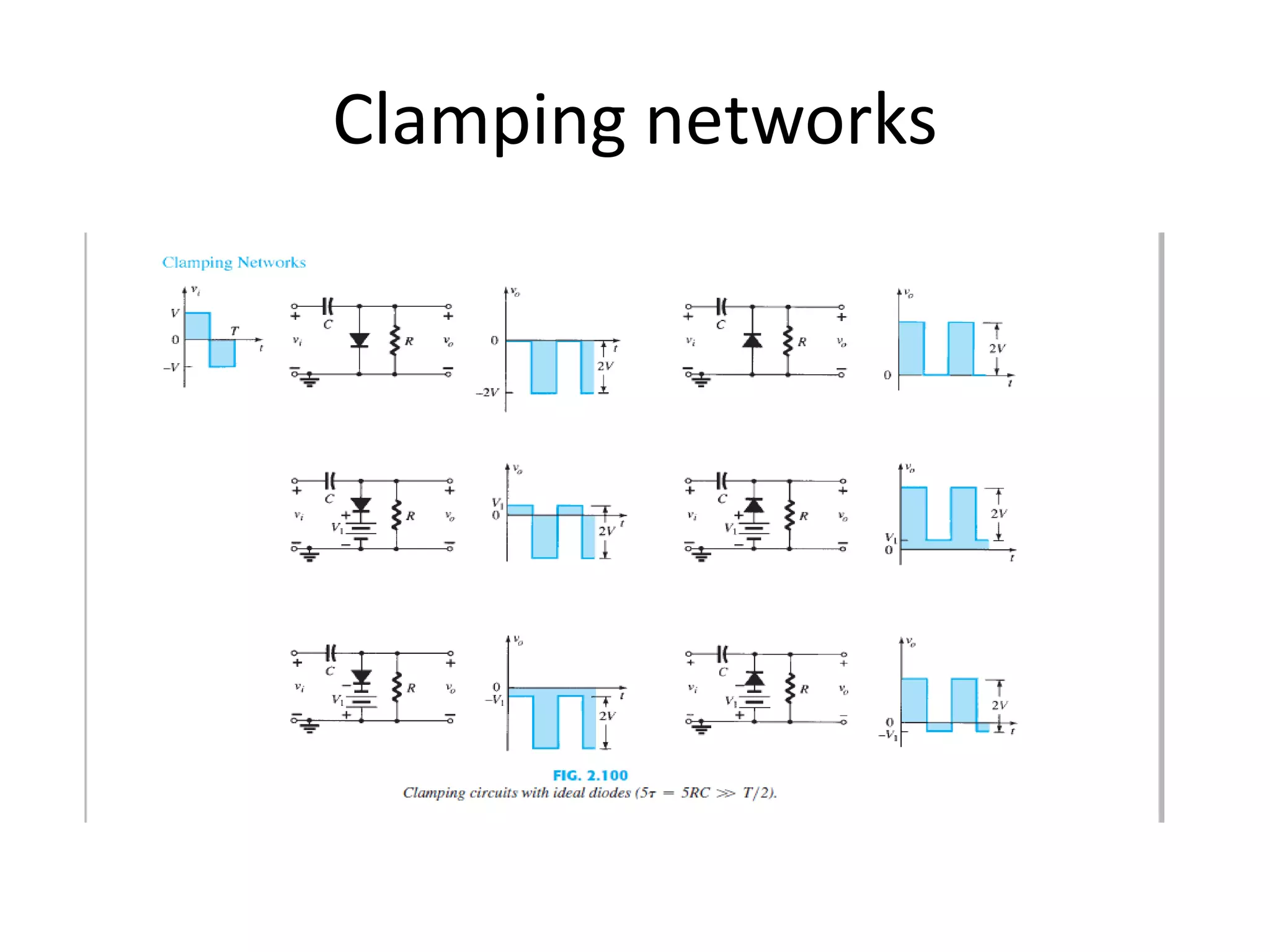
Clampers are electronic circuits that shift a waveform to a different voltage level without changing its appearance. There are two main types: positive clampers shift the input signal in a positive direction above a reference level, while negative clampers shift it in a negative direction below the reference. Clampers work by using diodes and capacitors to either pass or block portions of the input signal depending on its polarity, resulting in the output being shifted to a different DC level from the input but retaining the same AC waveform. They are commonly used in applications like test equipment, radar, sonar, and television receivers.