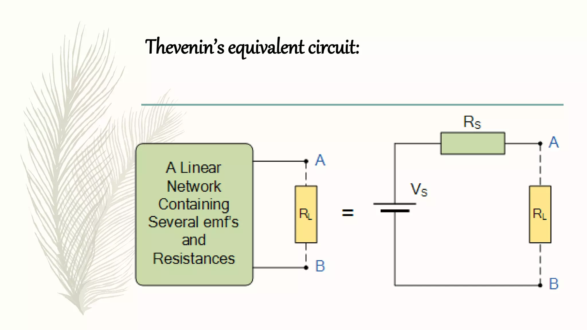
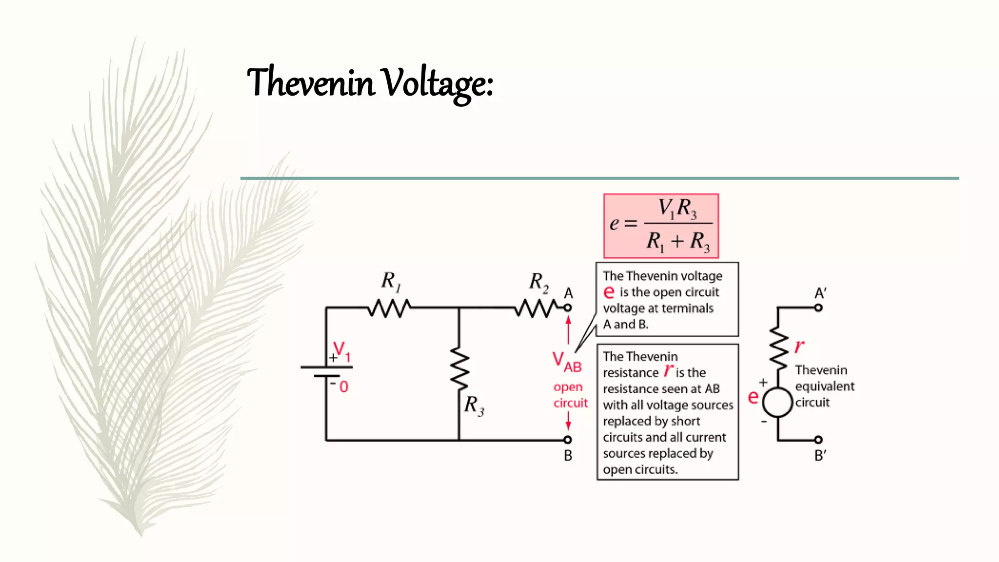
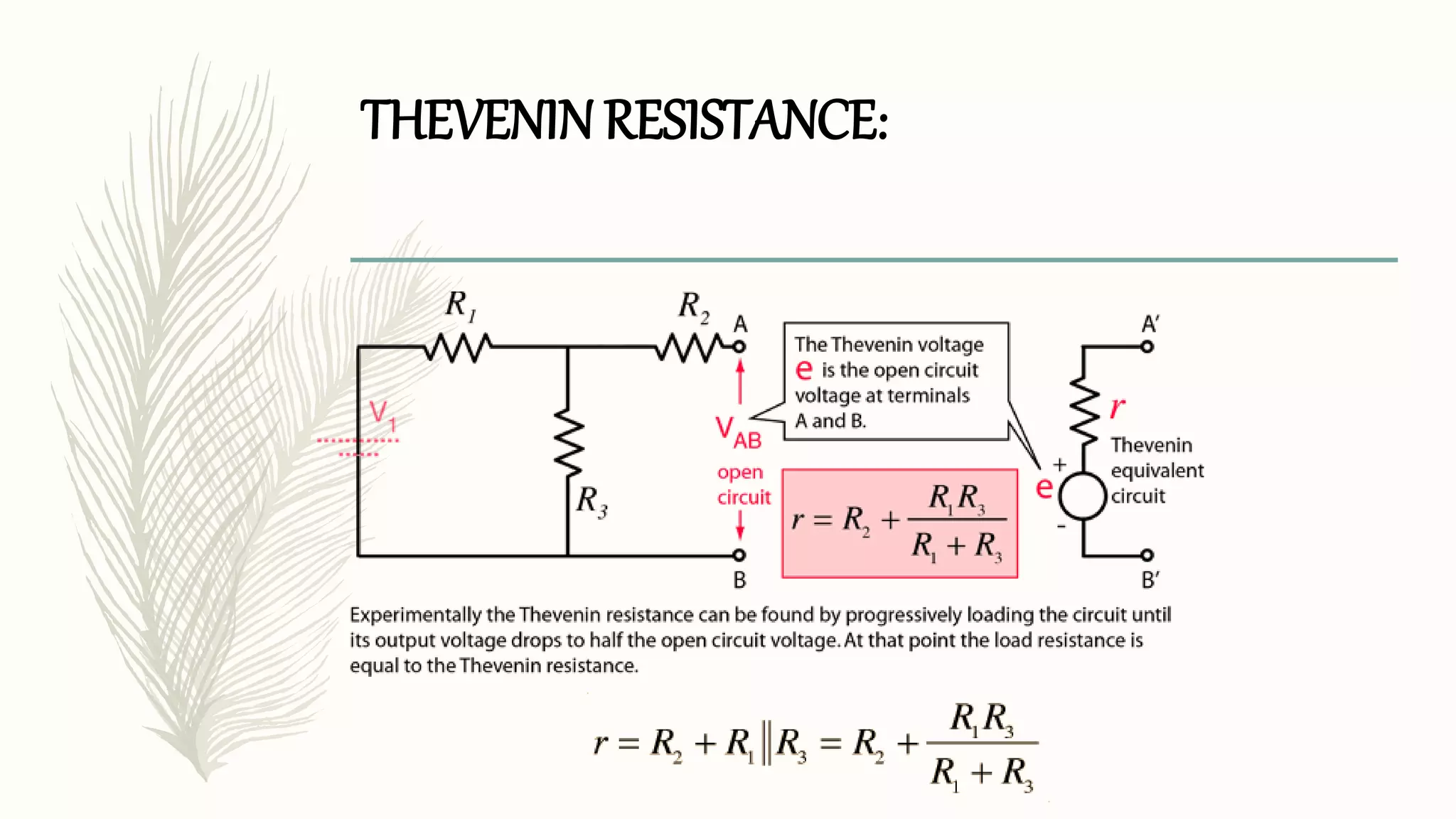
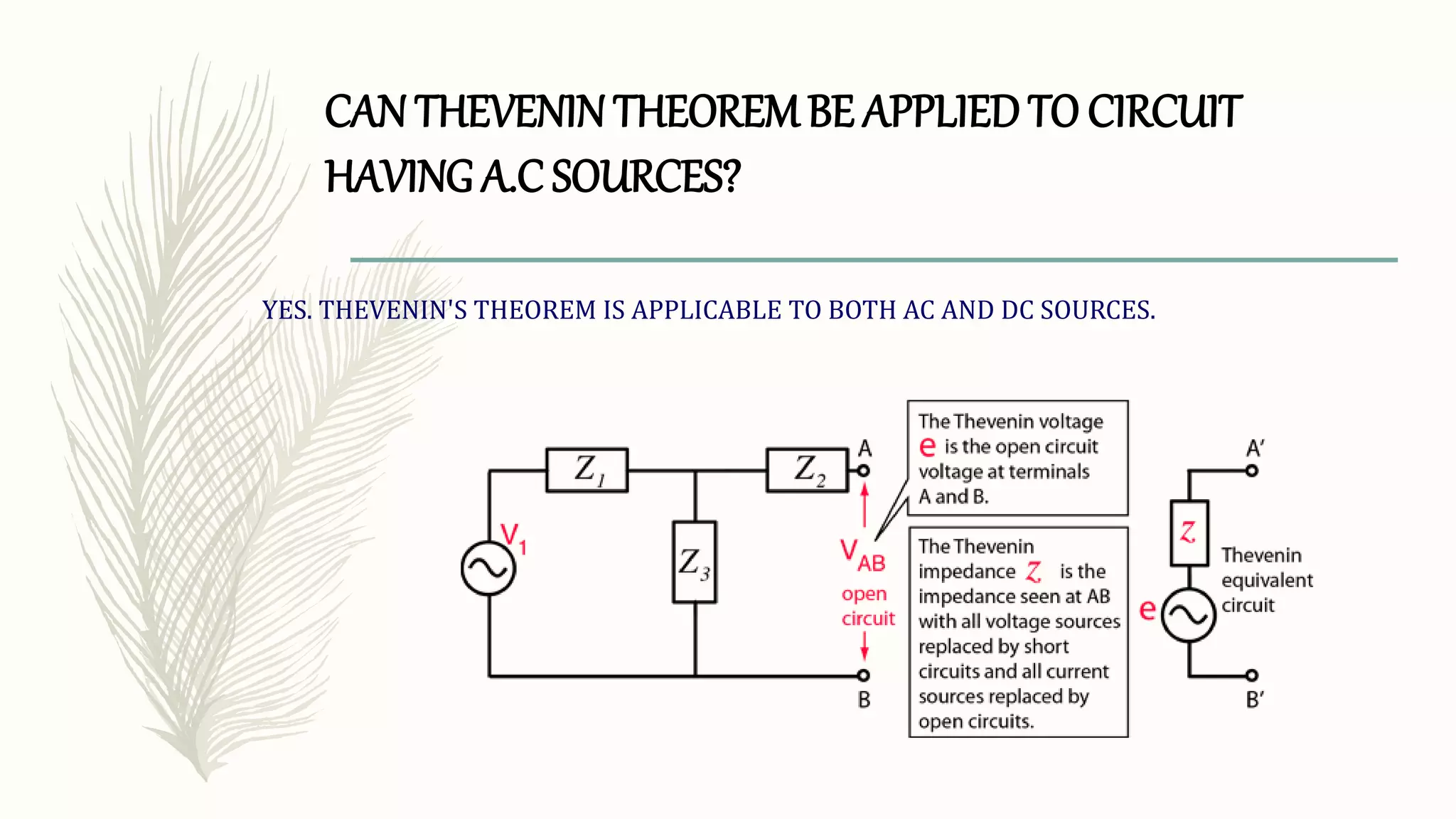
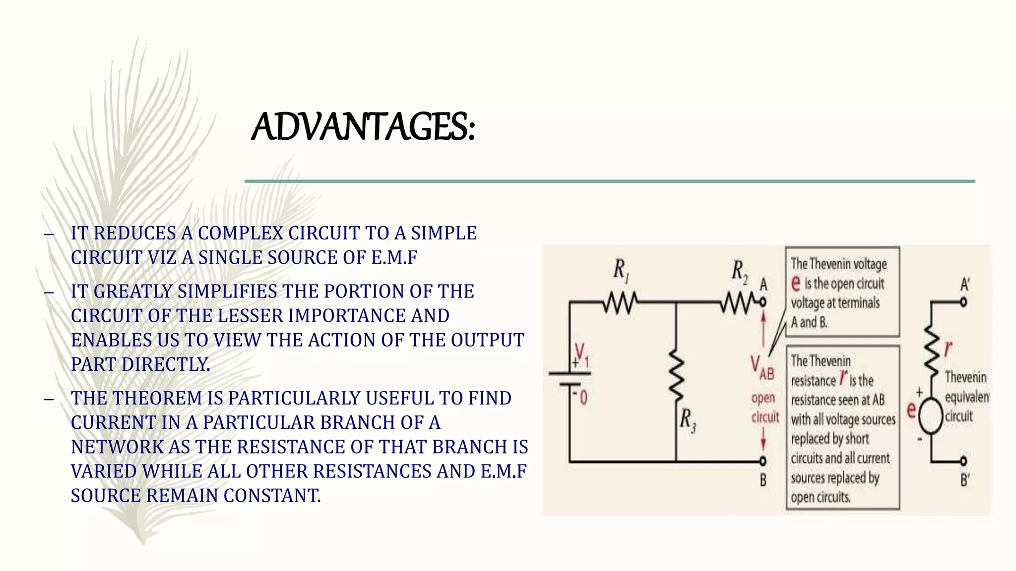
thevenin theorem. SLIDE NUMBER 3 EXPLANATION OF THEOREM: it is possible to simplify any electrical circuit, no matter how complex, to an equivalent two-terminal circuit with just a single constant voltage source in series with a resistance (or impedance) connected to a load. SLIDE NUMBER 4 INVENTION STORY THE THEOREM WAS INDEPENDENTLY DERIVED IN 1853 BY THE GERMAN SCIENTIST HERMANN VON HELMHOLTZ. SLIDE NUMBER 5 EXPLANATION OF Thevenin’s equivalent circuit As far as the load resistor RL is concerned, any complex “one-port” network consisting of multiple resistive circuit elements and energy sources can be replaced by one single equivalent resistance Rs and one single equivalent voltage Vs. Rs is the source resistance value looking back into the circuit and Vs is the open circuit voltage at the terminals. SLIDE NUMBER 6 EXPLANATION OF DIAGRAM 1 Let us consider a simple DC circuit as shown in the figure above, where we have to find the load current IL by the Thevenin’s theorem. In order to find the equivalent voltage source, rL is removed from the circuit as shown in the figure below and Voc or VTH is calculated. SLIDE NUMBER 7 EXPLANATION OF DIAGRAM 2 Now, to find the internal resistance of the network (Thevenin’s resistance or equivalent resistance) in series with the open circuit voltage VOC , also known as Thevenin’s voltage VTH, the voltage source is removed or we can say it is deactivated by a short circuit (as the source does not have any internal resistance) SLIDE NUMBER 9 As per Thevenin’s Statement, the load current is determined by the circuit shown above and the equivalent Thevenin’s circuit is obtained. Where, VTH is the Thevenin’s equivalent voltage. It is an open circuit voltage across the terminal AB known as load terminal RTH is the Thevenin’s equivalent resistance, as seen from the load terminals where all the sources are replaced by their internal impedance rL is the load resistance Steps for Solving Thevenin’s Theorem Step 1 – First of all remove the load resistance rL of the given circuit. Step 2 – Replace all the impedance source by their internal resistance. Step 3 – If sources are ideal then short circuit the voltage source and open the current source. Step 4 – Now find the equivalent resistance at the load terminals know as Thevenin’s Resistance (RTH). Step 5 – Draw the Thevenin’s equivalent circuit by connecting the load resistance and after that determine the desired response. Slide number-10 Thevenin Voltage The Thevenin voltage e used in Thevenin's Theorem is an ideal voltage source equal to the open circuit voltage at the terminals. In the example below, the resistance R2 does not affect this voltage and the resistances R1 and R3 form a voltage divider Slide number-11 Thevinin resistance The Thevenin resistance r used in Thevenin's Theorem is the resistance measured at terminals AB with all voltage sources replaced by short circuits and all current sources replaced by open circuits.