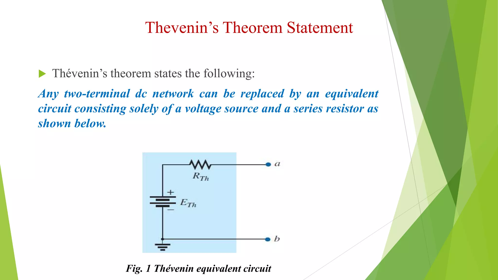
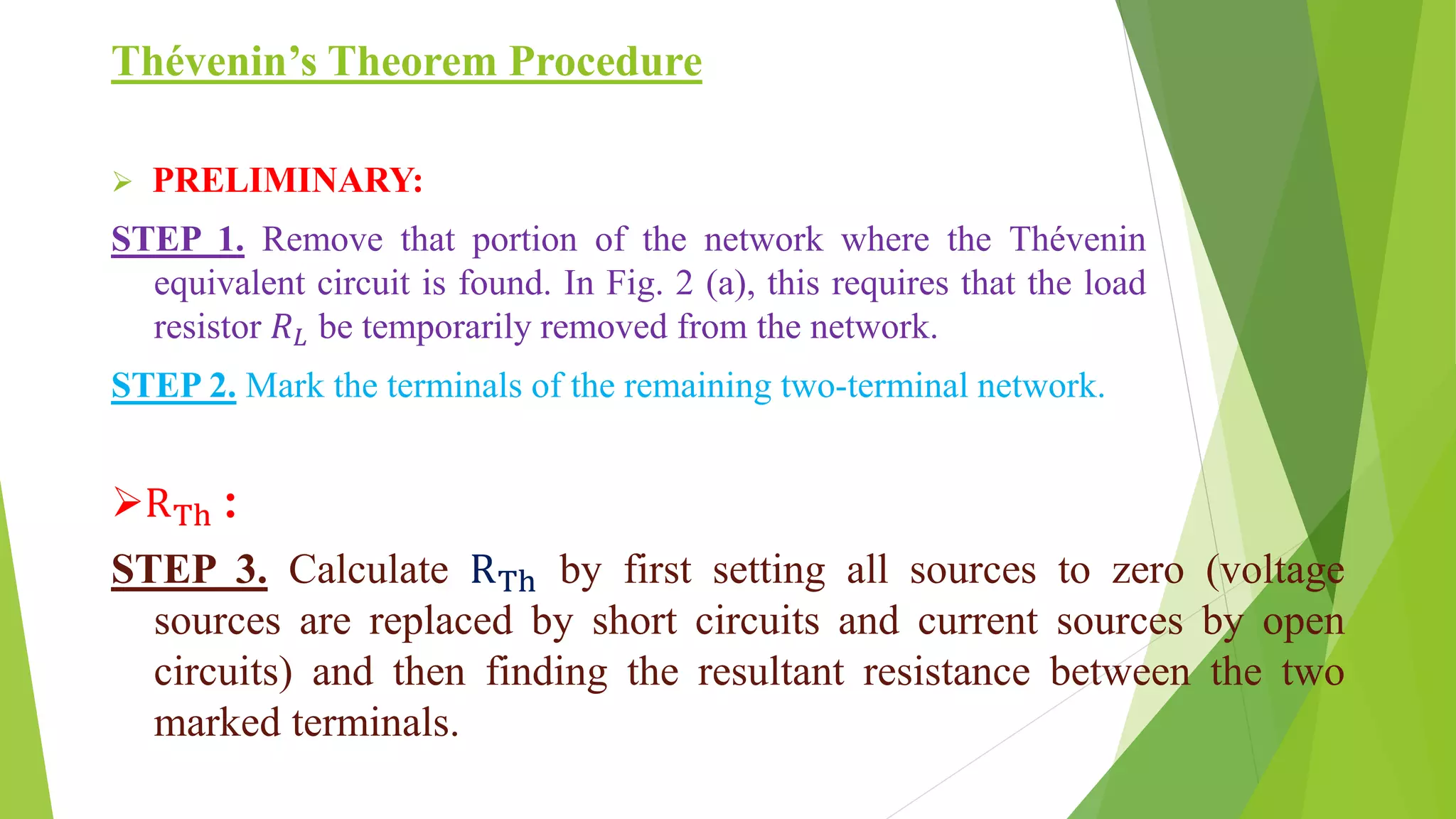
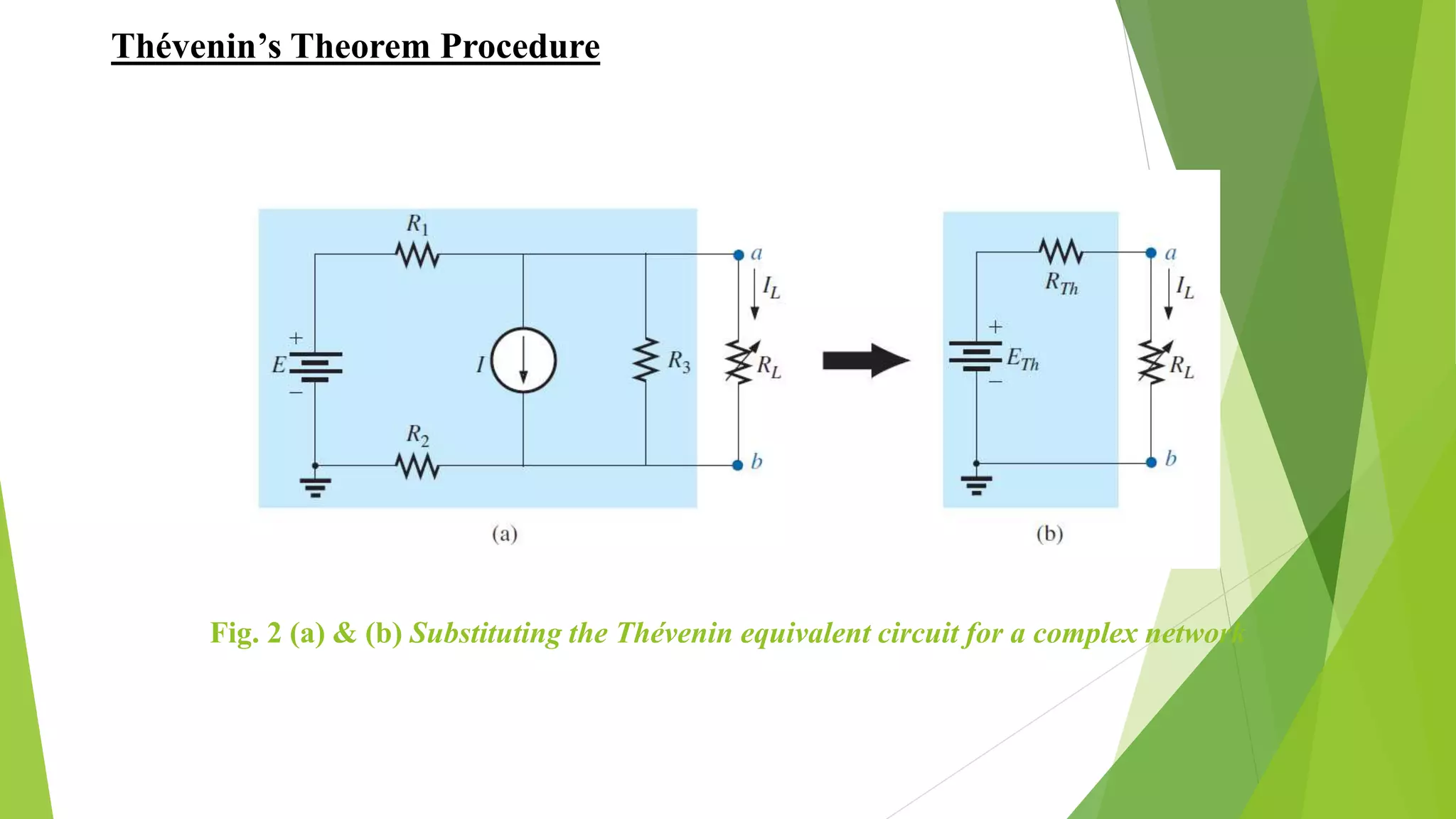
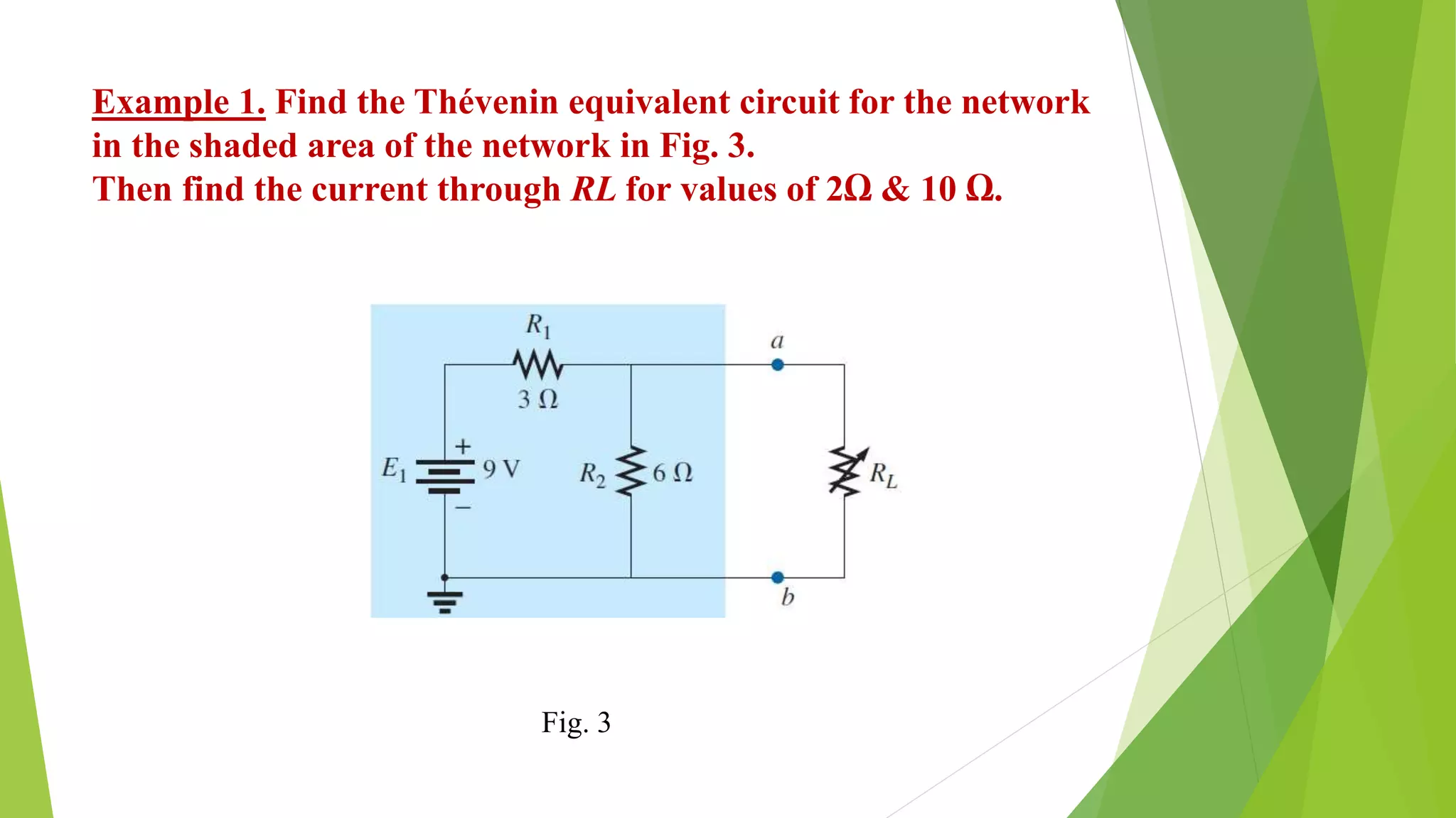
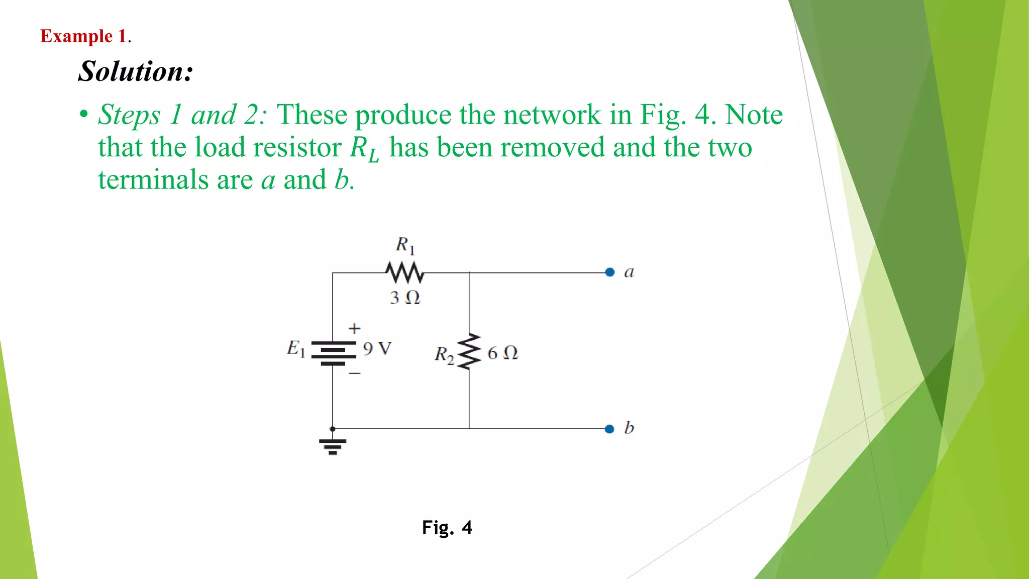
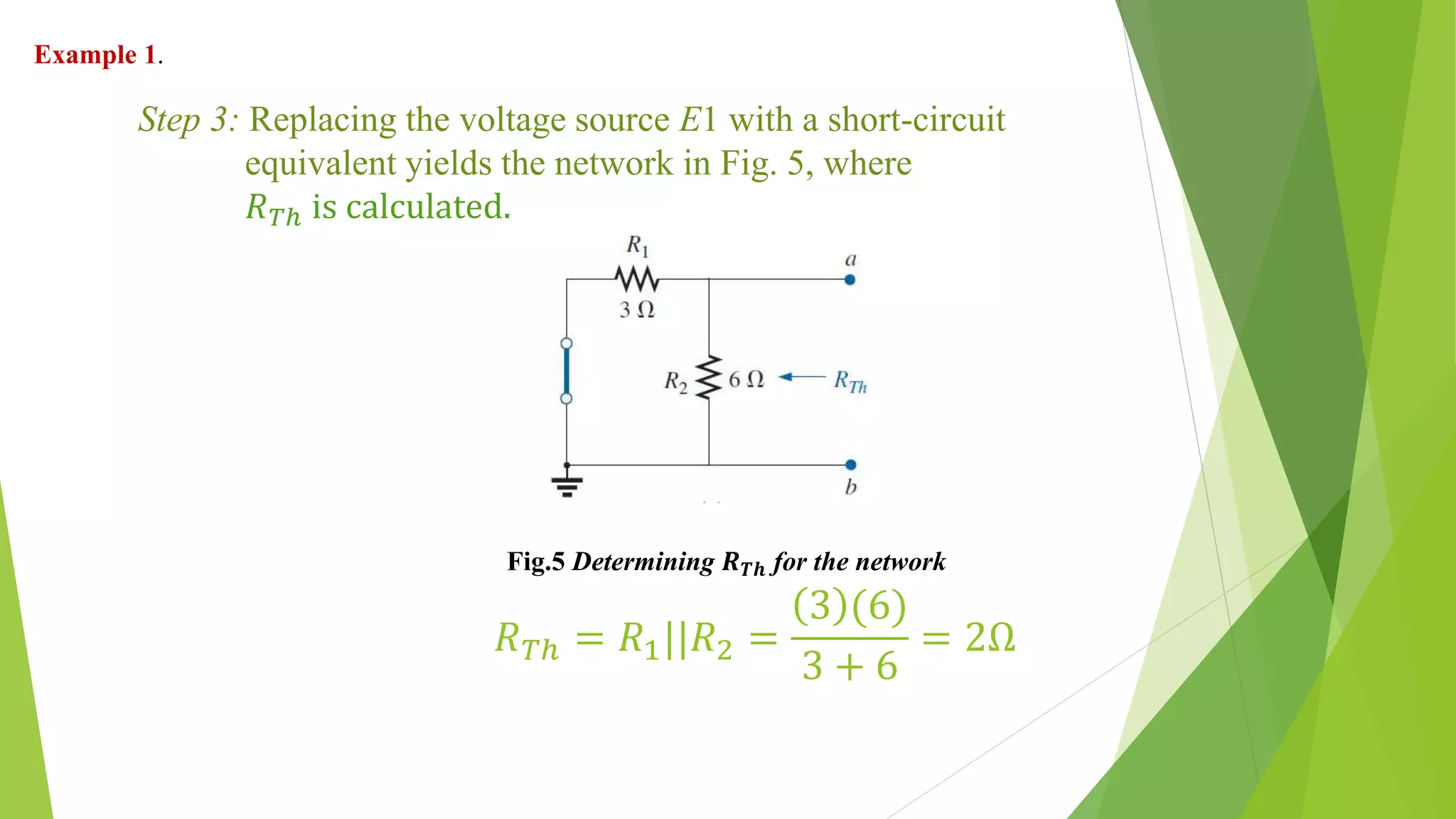
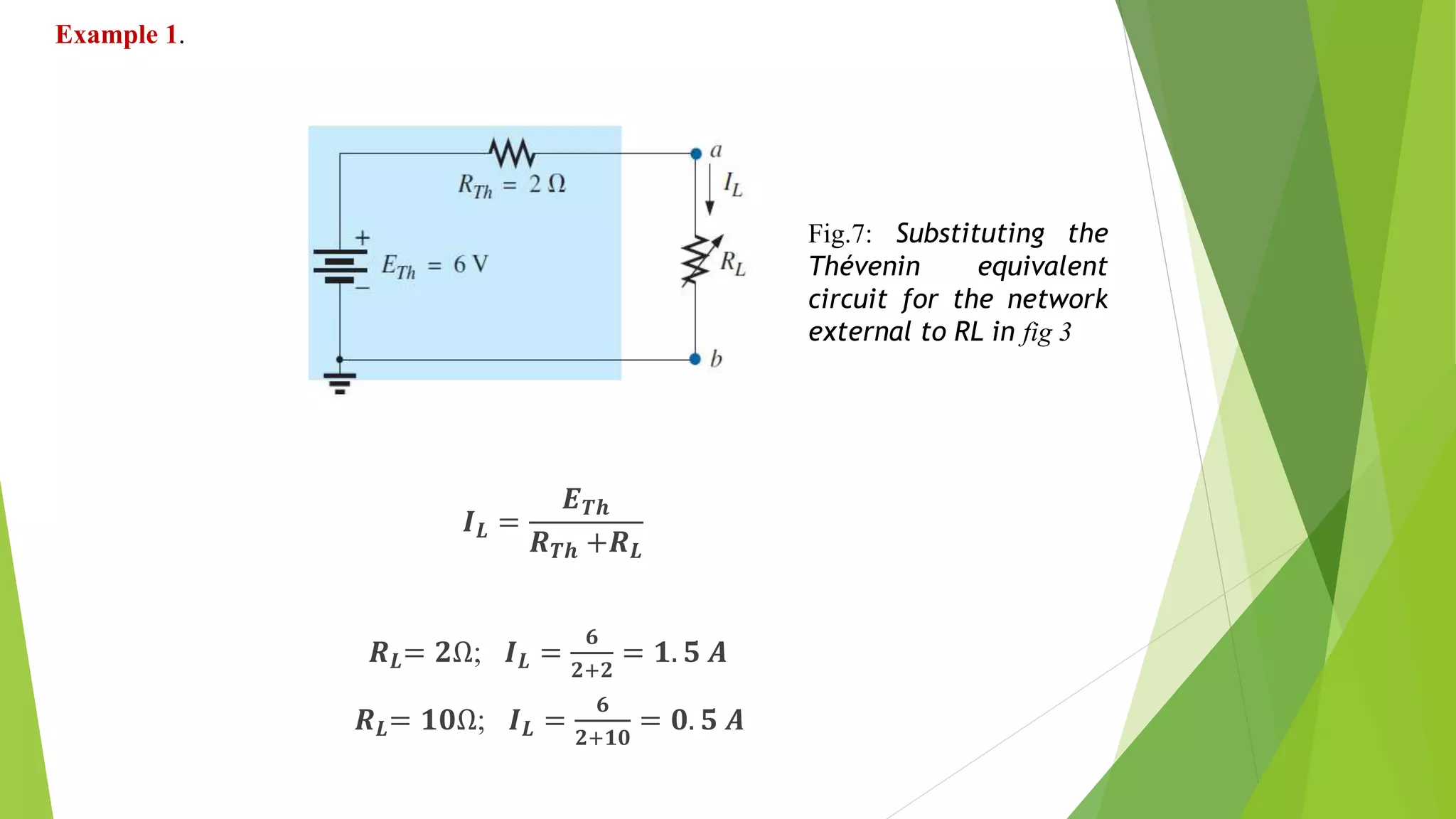
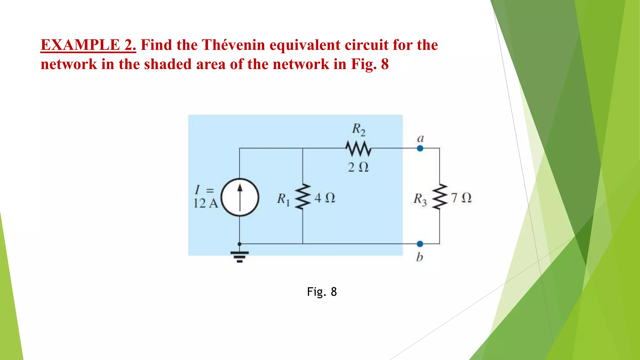
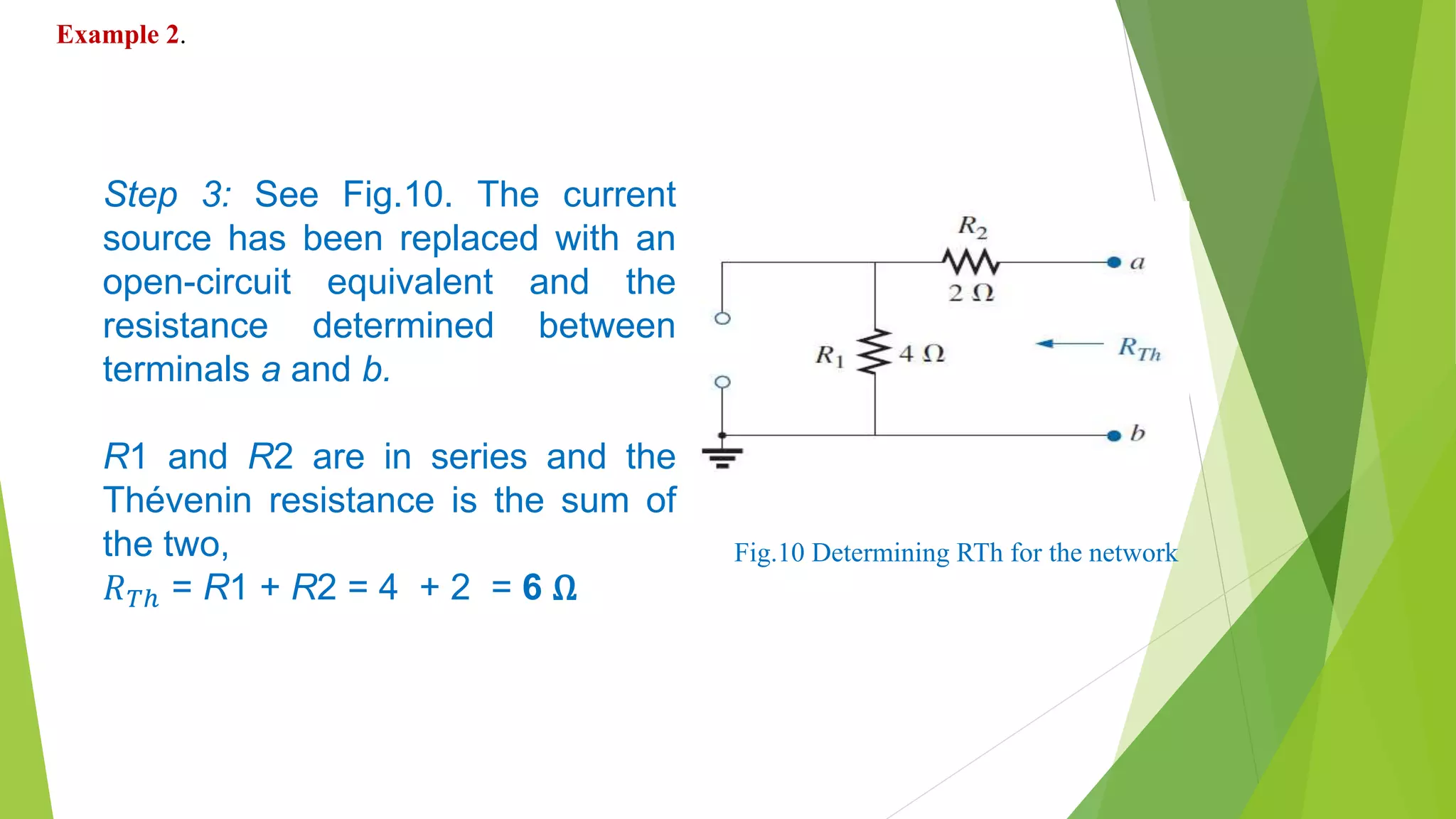
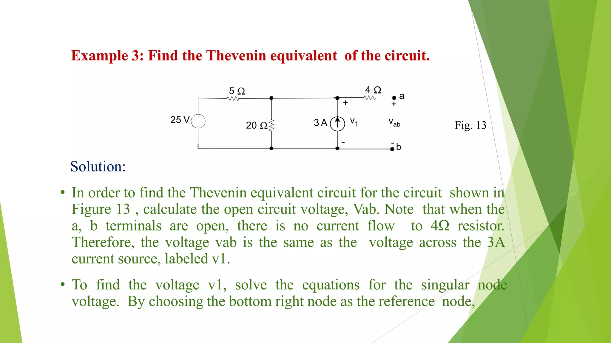
Thevenin’s Theorem
By-
Rajni Maurya
MITS, Gwalior
rajni.maurya2790@gmail.com
Thevenin’s Theorem Statement
 Thévenin’s theorem states the following:
Any two-terminal dc network can be replaced by an equivalent
circuit consisting solely of a voltage source and a series resistor as
shown below.
Fig. 1 Thévenin equivalent circuit
Thévenin’s Theorem Procedure
 PRELIMINARY:
STEP 1. Remove that portion of the network where the Thévenin
equivalent circuit is found. In Fig. 2 (a), this requires that the load
resistor 𝑅 𝐿 be temporarily removed from the network.
STEP 2. Mark the terminals of the remaining two-terminal network.
RTh :
STEP 3. Calculate RTh by first setting all sources to zero (voltage
sources are replaced by short circuits and current sources by open
circuits) and then finding the resultant resistance between the two
marked terminals.
Thévenin’s Theorem Procedure
 ETh :
STEP 4. Calculate ETh by first returning all sources to their original
position and finding the open-circuit voltage between the marked
terminals.
Conclusion:
STEP 5. Draw the Thévenin equivalent circuit with the portion of
the circuit previously removed replaced between the terminals
of the equivalent circuit. This step is indicated by the placement
of the resistor RL between the terminals of the Thévenin
equivalent circuit as shown in Fig. 2 (b)
Fig. 2 (a) & (b) Substituting the Thévenin equivalent circuit for a complex network
Thévenin’s Theorem Procedure
Example 1. Find the Thévenin equivalent circuit for the network
in the shaded area of the network in Fig. 3.
Then find the current through RL for values of 2Ω & 10 Ω.
Fig. 3
Solution:
• Steps 1 and 2: These produce the network in Fig. 4. Note
that the load resistor 𝑅 𝐿 has been removed and the two
terminals are a and b.
Fig. 4
Example 1.
𝑅 𝑇ℎ = 𝑅1||𝑅2 =
3 (6)
3 + 6
= 2Ω
Fig.5 Determining 𝑹 𝑻𝒉 for the network
Step 3: Replacing the voltage source E1 with a short-circuit
equivalent yields the network in Fig. 5, where
𝑅 𝑇ℎ is calculated.
Example 1.
 Step 4: Replace the voltage source (Fig.6) . For this case, the open
circuit voltage ETh is the same as the voltage drop across the 6Ω
resistor.
Applying the voltage divider rule gives
ETh =
R1R2
R1 + R2
=
(6)(9)
6 + 9
=
54
6 + 3
= 6V
Fig.6: Determining 𝑬 𝑻𝒉 for the network in fig 4
Example 1.
𝑰 𝑳 =
𝑬 𝑻𝒉
𝑹 𝑻𝒉 +𝑹 𝑳
𝑹 𝑳= 𝟐Ω; 𝑰 𝑳 =
𝟔
𝟐+𝟐
= 𝟏. 𝟓 𝑨
𝑹 𝑳= 𝟏𝟎Ω; 𝑰 𝑳 =
𝟔
𝟐+𝟏𝟎
= 𝟎. 𝟓 𝑨
Fig.7: Substituting the
Thévenin equivalent
circuit for the network
external to RL in fig 3
Example 1.
EXAMPLE 2. Find the Thévenin equivalent circuit for the
network in the shaded area of the network in Fig. 8
Fig. 8
 Steps 1 and 2:
The load resistor 𝑅 𝐿 has been removed and the two terminals are a and b.
Fig. 9
Example 2.
Solution:
Step 3: See Fig.10. The current
source has been replaced with an
open-circuit equivalent and the
resistance determined between
terminals a and b.
R1 and R2 are in series and the
Thévenin resistance is the sum of
the two,
𝑅 𝑇ℎ = R1 + R2 = 4 + 2 = 6 Ω
Fig.10 Determining RTh for the network
Example 2.
𝑉2 = 𝐼2. 𝑅2 = (0)R2 = 0 V
and
𝐸 𝑇ℎ = 𝑉1 = 𝐼1. 𝑅1 = 𝐼. 𝑅1
= (12 A)(4 Ω )
= 48 V
Fig. 11 Determining 𝑬 𝑻𝒉 for the network
Example 2.
Step 4: See Fig. 11. In this case, since an open circuit exists between
the terminals a & b, the current is zero between these terminals and
through the 2Ω resistor.
The voltage drop across R2 is, therefore,
 Step 5: See Fig. 12
Fig. 12 Substituting the Thévenin equivalent circuit in the
network external to the resistor R3 in Fig. 8
Example 2.
Example 3: Find the Thevenin equivalent of the circuit.
Solution:
• In order to find the Thevenin equivalent circuit for the circuit shown in
Figure 13 , calculate the open circuit voltage, Vab. Note that when the
a, b terminals are open, there is no current flow to 4Ω resistor.
Therefore, the voltage vab is the same as the voltage across the 3A
current source, labeled v1.
• To find the voltage v1, solve the equations for the singular node
voltage. By choosing the bottom right node as the reference node,
25 V
20
+
-
v13 A
5 4
+
vab
- b
a
Fig. 13
• By solving the equation, V1 = 32 V. Therefore, the Thevenin
voltage VTh for the circuit is 32 V.
• The next step is to short circuit the terminals and find the
short circuit current for the circuit shown in Figure 14.
( Note that the current is in the same direction as the falling
voltage at the terminal.)
3 0
5 20
v1 25 v1
25V
20
+
-
v23A
5
-
+
vab
4 a
b
isc
Figure 14
Example 3
0
4
v2
3
20
v2 25 v2
5
Current isc can be found if v2 is known. By using the bottom right
node as the reference node, the equationfor v2 becomes
By solving the above equation, v2 = 16 V.Therefore, the short
Circuit current
isc
The Thevenin resistance
RTh is
Example 3
Figure 15: Thevenin equivalent circuit for the Figure 1
Example 3
THANKS

Thevenin theorem

  • 1.
    Thevenin’s Theorem By- Rajni Maurya MITS,Gwalior rajni.maurya2790@gmail.com
  • 2.
    Thevenin’s Theorem Statement Thévenin’s theorem states the following: Any two-terminal dc network can be replaced by an equivalent circuit consisting solely of a voltage source and a series resistor as shown below. Fig. 1 Thévenin equivalent circuit
  • 3.
    Thévenin’s Theorem Procedure PRELIMINARY: STEP 1. Remove that portion of the network where the Thévenin equivalent circuit is found. In Fig. 2 (a), this requires that the load resistor 𝑅 𝐿 be temporarily removed from the network. STEP 2. Mark the terminals of the remaining two-terminal network. RTh : STEP 3. Calculate RTh by first setting all sources to zero (voltage sources are replaced by short circuits and current sources by open circuits) and then finding the resultant resistance between the two marked terminals.
  • 4.
    Thévenin’s Theorem Procedure ETh : STEP 4. Calculate ETh by first returning all sources to their original position and finding the open-circuit voltage between the marked terminals. Conclusion: STEP 5. Draw the Thévenin equivalent circuit with the portion of the circuit previously removed replaced between the terminals of the equivalent circuit. This step is indicated by the placement of the resistor RL between the terminals of the Thévenin equivalent circuit as shown in Fig. 2 (b)
  • 5.
    Fig. 2 (a)& (b) Substituting the Thévenin equivalent circuit for a complex network Thévenin’s Theorem Procedure
  • 6.
    Example 1. Findthe Thévenin equivalent circuit for the network in the shaded area of the network in Fig. 3. Then find the current through RL for values of 2Ω & 10 Ω. Fig. 3
  • 7.
    Solution: • Steps 1and 2: These produce the network in Fig. 4. Note that the load resistor 𝑅 𝐿 has been removed and the two terminals are a and b. Fig. 4 Example 1.
  • 8.
    𝑅 𝑇ℎ =𝑅1||𝑅2 = 3 (6) 3 + 6 = 2Ω Fig.5 Determining 𝑹 𝑻𝒉 for the network Step 3: Replacing the voltage source E1 with a short-circuit equivalent yields the network in Fig. 5, where 𝑅 𝑇ℎ is calculated. Example 1.
  • 9.
     Step 4:Replace the voltage source (Fig.6) . For this case, the open circuit voltage ETh is the same as the voltage drop across the 6Ω resistor. Applying the voltage divider rule gives ETh = R1R2 R1 + R2 = (6)(9) 6 + 9 = 54 6 + 3 = 6V Fig.6: Determining 𝑬 𝑻𝒉 for the network in fig 4 Example 1.
  • 10.
    𝑰 𝑳 = 𝑬𝑻𝒉 𝑹 𝑻𝒉 +𝑹 𝑳 𝑹 𝑳= 𝟐Ω; 𝑰 𝑳 = 𝟔 𝟐+𝟐 = 𝟏. 𝟓 𝑨 𝑹 𝑳= 𝟏𝟎Ω; 𝑰 𝑳 = 𝟔 𝟐+𝟏𝟎 = 𝟎. 𝟓 𝑨 Fig.7: Substituting the Thévenin equivalent circuit for the network external to RL in fig 3 Example 1.
  • 11.
    EXAMPLE 2. Findthe Thévenin equivalent circuit for the network in the shaded area of the network in Fig. 8 Fig. 8
  • 12.
     Steps 1and 2: The load resistor 𝑅 𝐿 has been removed and the two terminals are a and b. Fig. 9 Example 2. Solution:
  • 13.
    Step 3: SeeFig.10. The current source has been replaced with an open-circuit equivalent and the resistance determined between terminals a and b. R1 and R2 are in series and the Thévenin resistance is the sum of the two, 𝑅 𝑇ℎ = R1 + R2 = 4 + 2 = 6 Ω Fig.10 Determining RTh for the network Example 2.
  • 14.
    𝑉2 = 𝐼2.𝑅2 = (0)R2 = 0 V and 𝐸 𝑇ℎ = 𝑉1 = 𝐼1. 𝑅1 = 𝐼. 𝑅1 = (12 A)(4 Ω ) = 48 V Fig. 11 Determining 𝑬 𝑻𝒉 for the network Example 2. Step 4: See Fig. 11. In this case, since an open circuit exists between the terminals a & b, the current is zero between these terminals and through the 2Ω resistor. The voltage drop across R2 is, therefore,
  • 15.
     Step 5:See Fig. 12 Fig. 12 Substituting the Thévenin equivalent circuit in the network external to the resistor R3 in Fig. 8 Example 2.
  • 16.
    Example 3: Findthe Thevenin equivalent of the circuit. Solution: • In order to find the Thevenin equivalent circuit for the circuit shown in Figure 13 , calculate the open circuit voltage, Vab. Note that when the a, b terminals are open, there is no current flow to 4Ω resistor. Therefore, the voltage vab is the same as the voltage across the 3A current source, labeled v1. • To find the voltage v1, solve the equations for the singular node voltage. By choosing the bottom right node as the reference node, 25 V 20 + - v13 A 5 4 + vab - b a Fig. 13
  • 17.
    • By solvingthe equation, V1 = 32 V. Therefore, the Thevenin voltage VTh for the circuit is 32 V. • The next step is to short circuit the terminals and find the short circuit current for the circuit shown in Figure 14. ( Note that the current is in the same direction as the falling voltage at the terminal.) 3 0 5 20 v1 25 v1 25V 20 + - v23A 5 - + vab 4 a b isc Figure 14 Example 3
  • 18.
    0 4 v2 3 20 v2 25 v2 5 Currentisc can be found if v2 is known. By using the bottom right node as the reference node, the equationfor v2 becomes By solving the above equation, v2 = 16 V.Therefore, the short Circuit current isc The Thevenin resistance RTh is Example 3
  • 19.
    Figure 15: Theveninequivalent circuit for the Figure 1 Example 3
  • 20.