Downloaded 646 times
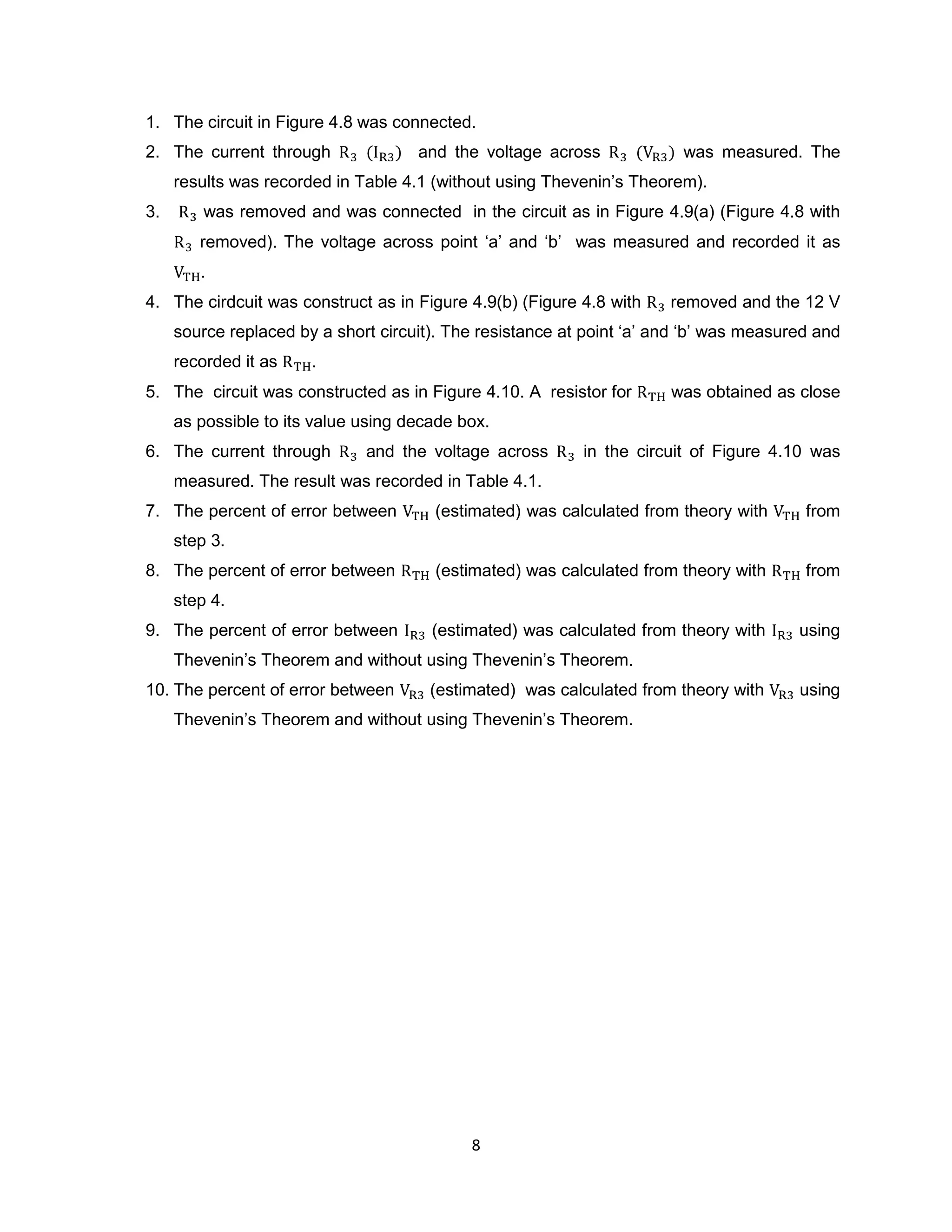
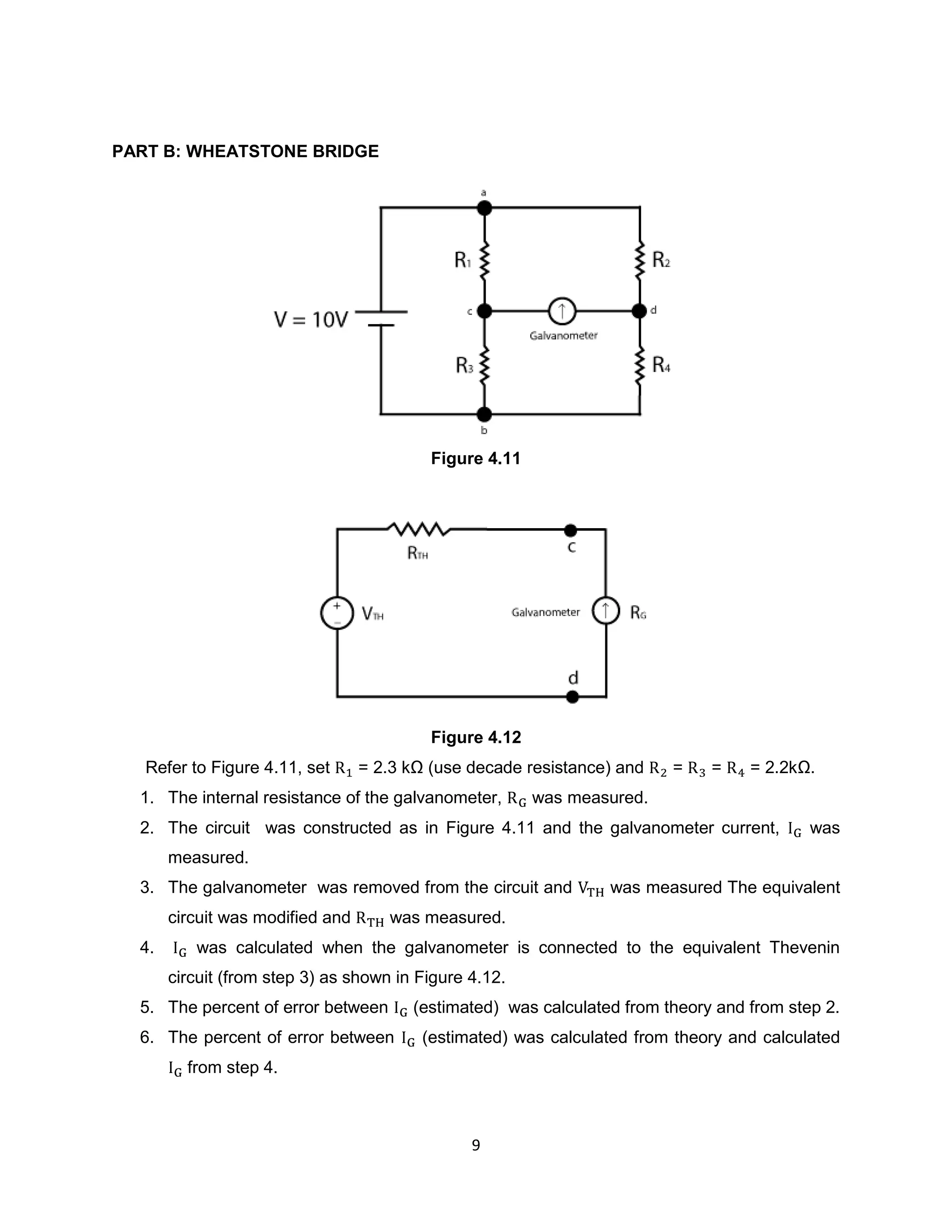

1) The document describes an experiment to analyze DC resistive circuits using Thevenin's Theorem and analyze an unbalanced Wheatstone bridge. 2) Key aspects of the experiment include using Thevenin's Theorem to determine equivalent resistance (Rth) and voltage (Vth) for circuits, and analyzing how these values change when measuring a Wheatstone bridge circuit with an unknown resistance. 3) Results showed differences between estimated and measured values for currents and voltages due to experimental errors like resistance in connecting wires. Thevenin's Theorem was useful for simplifying complex circuits into equivalent components.


