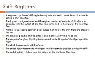
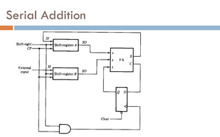
1. The document discusses different types of registers, counters, and shift registers including their components, functions, and loading/shifting processes.
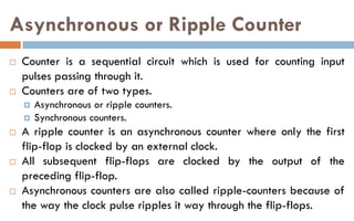
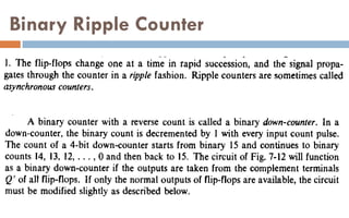
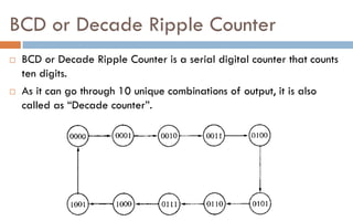
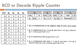
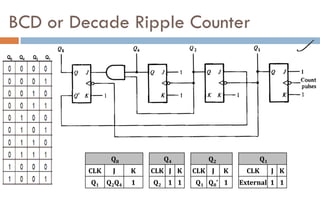
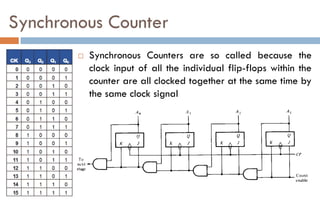
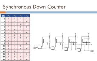
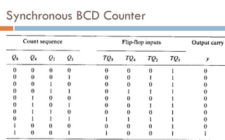
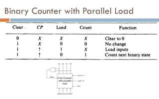
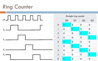
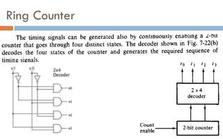
2. It also covers synchronous and asynchronous counters as well as ring and Johnson counters.
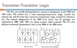
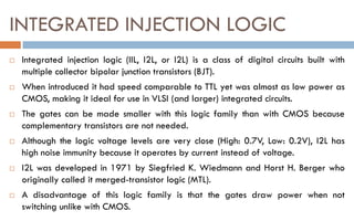
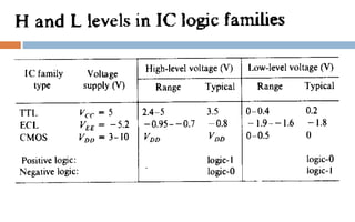
3. Finally, it discusses integrated circuits and different digital logic families including TTL, ECL, MOS, CMOS, and I2L.