Sequential Circuits 3
SequentialCircuits
Sequential Circuits
Combinational
Combinational
The outputs depend only on the current input values
The outputs depend only on the current input values
It uses only logic gates
It uses only logic gates
Sequential
Sequential
The outputs depend on the current and past input
The outputs depend on the current and past input
values
values
It uses logic gates and storage elements
It uses logic gates and storage elements
Example
Example
Vending machine
Vending machine
They are referred as finite state machines since they
They are referred as finite state machines since they
have a finite number of states
have a finite number of states
4.
Sequential Circuits 4
BlockDiagram
Block Diagram
Memory elements can store binary
Memory elements can store binary
information
information
This information at any given time determines the
This information at any given time determines the
state of the circuit at that time
state of the circuit at that time
5.
Sequential Circuits 5
SequentialCircuit Types
Sequential Circuit Types
Synchronous
Synchronous
The circuit behavior is determined by the signals
The circuit behavior is determined by the signals
at discrete instants of time
at discrete instants of time
The memory elements are affected only at
The memory elements are affected only at
discrete instants of time
discrete instants of time
A clock is used for synchronization
A clock is used for synchronization
Memory elements are affected only with the arrival
Memory elements are affected only with the arrival
of a clock pulse
of a clock pulse
If memory elements use clock pulses in their
If memory elements use clock pulses in their
inputs, the circuit is called
inputs, the circuit is called
Clocked sequential circuit
Clocked sequential circuit
6.
Sequential Circuits 6
SequentialCircuit Types
Sequential Circuit Types
ASynchronous
ASynchronous
The circuit behavior is determined by the signals
The circuit behavior is determined by the signals
at any instant of time
at any instant of time
It is also affected by the order the inputs change
It is also affected by the order the inputs change
7.
Sequential Circuits 7
Clock
Clock
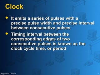
It emits a series of pulses with a
It emits a series of pulses with a
precise pulse width and precise interval
precise pulse width and precise interval
between consecutive pulses
between consecutive pulses
Timing interval between the
Timing interval between the
corresponding edges of two
corresponding edges of two
consecutive pulses is known as the
consecutive pulses is known as the
clock cycle time, or period
clock cycle time, or period
Sequential Circuits 9
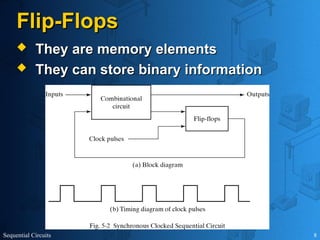
Flip-Flops
Flip-Flops
Can keep a binary state until an input
Can keep a binary state until an input
signal to switch the state is received
signal to switch the state is received
There are different types of flip-flops
There are different types of flip-flops
depending on the number of inputs and
depending on the number of inputs and
how the inputs affect the binary state
how the inputs affect the binary state
10.
Sequential Circuits 10
Latches
Latches
The most basic flip-flops
The most basic flip-flops
They operate with signal levels
They operate with signal levels
The flip-flops are constructed from
The flip-flops are constructed from
latches
latches
They are not useful for
They are not useful for synchronous
synchronous
sequential circuits
sequential circuits
They are useful for
They are useful for asynchronous
asynchronous
sequential circuits
sequential circuits
Sequential Circuits 12
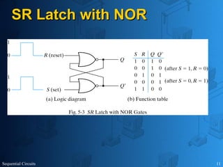
SRLatch with NOR
SR Latch with NOR
1
R
1,
S
avoid
,
conditions
normal
In
0
set to
are
Q'
and
Q
undefined,
1
R
1,
S
state
reset
1
'
,
0
state
set
0
'
,
1
Q
Q
Q
Q
reset
R
set
S
Sequential Circuits 14
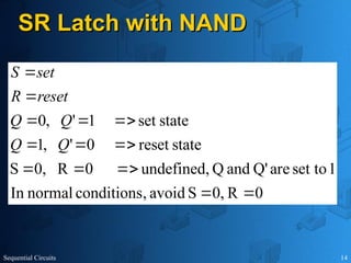
SRLatch with NAND
SR Latch with NAND
0
R
0,
S
avoid
,
conditions
normal
In
1
set to
are
Q'
and
Q
undefined,
0
R
0,
S
state
reset
0
'
,
1
state
set
1
'
,
0
Q
Q
Q
Q
reset
R
set
S
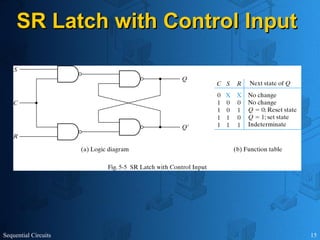
Sequential Circuits 18
Note
Note
The control input changes the state of a
The control input changes the state of a
latch or flip-flop
latch or flip-flop
The momentary change is called a
The momentary change is called a
trigger
trigger
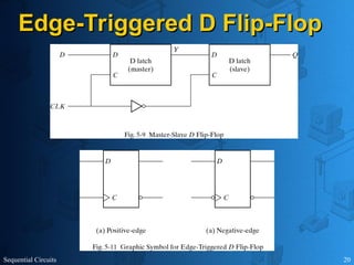
Example: D Latch
Example: D Latch
It is triggered every time the pulse goes to the
It is triggered every time the pulse goes to the
logic level 1
logic level 1
As long as the pulse remains at the logic level 1,
As long as the pulse remains at the logic level 1,
the change in the data (D) directly affects the
the change in the data (D) directly affects the
output (Q)
output (Q)
THIS MAY BE A BIG PROBLEM since the state of
THIS MAY BE A BIG PROBLEM since the state of
the latch may keep changing depending on the
the latch may keep changing depending on the
input (may be coming from a combinational logic
input (may be coming from a combinational logic
network)
network)
19.
Sequential Circuits 19
Howto Solve?
How to Solve?
Trigger the flip-flop only during a signal
Trigger the flip-flop only during a signal
transition
transition
Sequential Circuits 26
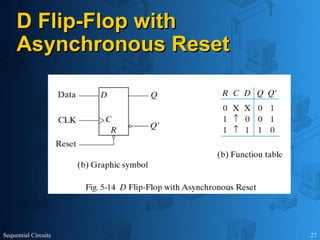
DirectInputs
Direct Inputs
You can use asynchronous inputs to
You can use asynchronous inputs to
put a flip-flop to a specific state
put a flip-flop to a specific state
regardless of the clock
regardless of the clock
You can clear the content of a flip-flop
You can clear the content of a flip-flop
The content is changed to zero (0)
The content is changed to zero (0)
This is called clear or direct reset
This is called clear or direct reset
This is particularly useful when the power is off
This is particularly useful when the power is off
The state of the flip-flop is set to unknown
The state of the flip-flop is set to unknown
Sequential Circuits 28
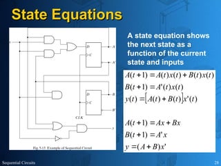
StateEquations
State Equations
'
)
(
'
)
1
(
)
1
(
)
(
'
)
(
)
(
)
(
)
(
)
(
'
)
1
(
)
(
)
(
)
(
)
(
)
1
(
x
B
A
y
x
A
t
B
Bx
Ax
t
A
t
x
t
B
t
A
t
y
t
x
t
A
t
B
t
x
t
B
t
x
t
A
t
A
A state equation shows
the next state as a
function of the current
state and inputs
Sequential Circuits 32
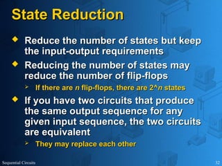
StateReduction
State Reduction
Reduce the number of states but keep
Reduce the number of states but keep
the input-output requirements
the input-output requirements
Reducing the number of states may
Reducing the number of states may
reduce the number of flip-flops
reduce the number of flip-flops
If there are
If there are n
n flip-flops, there are 2^
flip-flops, there are 2^n
n states
states
If you have two circuits that produce
If you have two circuits that produce
the same output sequence for any
the same output sequence for any
given input sequence, the two circuits
given input sequence, the two circuits
are equivalent
are equivalent
They may replace each other
They may replace each other
33.
Sequential Circuits 33
StateReduction Example
State Reduction Example
Find the states for which the
next states and outputs are
the same
34.
Sequential Circuits 34
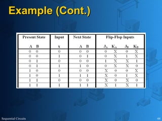
Example(Cont.)
Example (Cont.)
In the next
state, g is
replaced with e
In the next
state, f is
replaced with d
Sequential Circuits 36
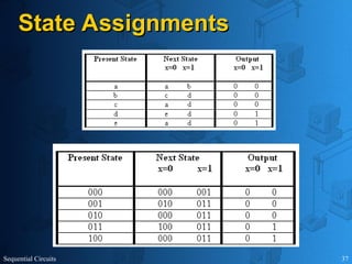
StateAssignment
State Assignment
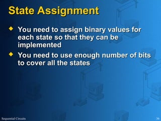
You need to assign binary values for
You need to assign binary values for
each state so that they can be
each state so that they can be
implemented
implemented
You need to use enough number of bits
You need to use enough number of bits
to cover all the states
to cover all the states
Sequential Circuits 38
DesignProcedure
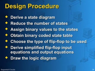
Design Procedure
Derive a state diagram
Derive a state diagram
Reduce the number of states
Reduce the number of states
Assign binary values to the states
Assign binary values to the states
Obtain binary coded state table
Obtain binary coded state table
Choose the type of flip-flop to be used
Choose the type of flip-flop to be used
Derive simplified flip-flop input
Derive simplified flip-flop input
equations and output equations
equations and output equations
Draw the logic diagram
Draw the logic diagram
39.
Sequential Circuits 39
Example
Example
Design a circuit (with D flip-flops) that
Design a circuit (with D flip-flops) that
detects three or more consecutive 1’s in a
detects three or more consecutive 1’s in a
string of bits coming through an input line
string of bits coming through an input line
40.
Sequential Circuits 40
Example(Cont.)
Example (Cont.)
7
,
6
)
,
,
(
7
,
5
,
1
)
,
,
(
)
1
(
7
,
5
,
3
)
,
,
(
)
1
(
x
B
A
y
x
B
A
D
t
B
x
B
A
D
t
A
B
A
Sequential Circuits 43
Example
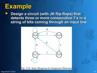
Example
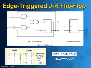
Design a circuit (with JK flip-flops) that
Design a circuit (with JK flip-flops) that
detects three or more consecutive 1’s in a
detects three or more consecutive 1’s in a
string of bits coming through an input line
string of bits coming through an input line
#1 ^*#{}#*^
SHOW merlin, merlin.acs, 83, 80
PLAY Confused
PLAY RestPose
PLAY Explain
SAY Welcome to the second lecture of the CS 311.
SAY Dr. Ali Sekmen will be teaching this class for this semester.
SAY He will have power point presentations for each lecture. Please feel free to ask any questions you have during the lectures.
2) SHOW genie, genie.acs, 10, 30
2) PLAY Greet
2) PLAY RestPose
2) SAY The details of the course are described in the handouts which were distributed at the beginning of the lecture.
SAY This course will provide you with a deep understanding of Java programming language.
SAY You will be developing both Java Applications and Java Applets.
3) SHOW peedy, peedy.acs, 10, 70
3) PLAY Greet
3) PLAY RestPose
3)SAY You will also develop some practical applications in graphics, multimedia, database connectivity, networking, and Internet.
4)SHOW robby, robby.acs, 80, 30
4)PLAY Greet
4) PLAY RestPose
2)SAY The prerequisite for this course is a grade of C or better in CS 212.
2) SAY Those who do not meet the prerequisite should withdraw this course.
4) SAY Java is much easier than C and C++ yet more powerful for Internet based developments.
3)HIDE
4)HIDE
SLIDE 2=MOVE 17,17


![Unit 2[1] . technology with the informationpptx](https://cdn.slidesharecdn.com/ss_thumbnails/unit21-250302040241-815cd69e-thumbnail.jpg?width=640&height=640&fit=bounds)


