Downloaded 399 times


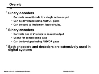
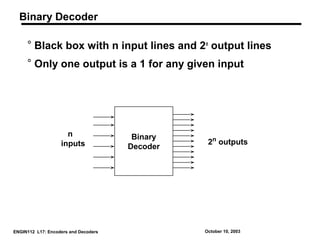

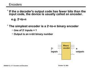
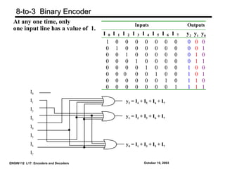


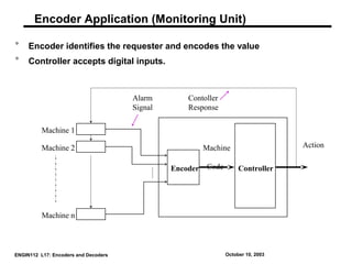
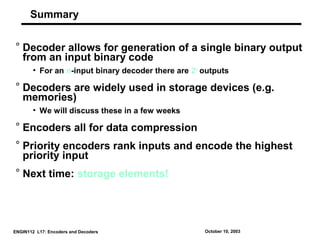

The document provides an overview of encoders and decoders in digital systems, detailing their functions and implementations. It explains binary decoders and encoders, their construction using logic gates, and includes examples of 2-to-4 and 3-to-8 decoders and their applications in combinational circuits. The document concludes with a discussion on priority encoders and their use in encoding the highest priority input, emphasizing the significance of these components in data compression and memory storage.