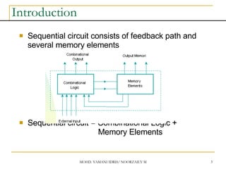
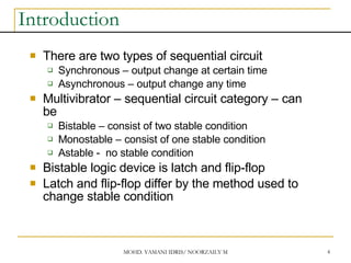
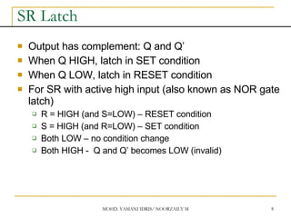
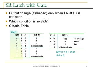
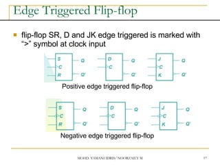
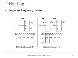
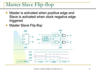
2. MOHD. YAMANI IDRIS/ NOORZAILY MOHAMED NOOR 2
Contents
Introduction
Memory Element
Latch
SR latch
D latch
Flip-flop
SR flip-flop
D flip-flop
JK flip-flop
T flip-flop
3. MOHD. YAMANI IDRIS/ NOORZAILY MOHAMED NOOR 3
Introduction
Sequential circuit consists of feedback path and
several memory elements
Sequential circuit = Combinational Logic +
Memory Elements
4. MOHD. YAMANI IDRIS/ NOORZAILY MOHAMED NOOR 4
Introduction
There are two types of sequential circuit
Synchronous – output change at certain time
Asynchronous – output change any time
Multivibrator – sequential circuit category – can
be
Bistable – consist of two stable condition
Monostable – consist of one stable condition
Astable - no stable condition
Bistable logic device is latch and flip-flop
Latch and flip-flop differ by the method used to
change stable condition
5. MOHD. YAMANI IDRIS/ NOORZAILY MOHAMED NOOR 5
Memory Element
Memory element device that can remember a
value for a certain period, or change value based
on the input instruction
Example: Latch and flip-flop
Commands for latches include set and reset
commands
6. MOHD. YAMANI IDRIS/ NOORZAILY MOHAMED NOOR 6
Memory Element
Flip-flop is a memory element which change its condition
based on clock signal
Clock is a square waveform
7. MOHD. YAMANI IDRIS/ NOORZAILY MOHAMED NOOR 7
Memory Element
There are two types of trigger/activator
Pulse triggered
Edge triggered
Pulse triggered
Latch
ON=1, OFF=0
Edge triggered
Flip-flop
Positive edge triggered (ON=when 0 to 1, OFF=other time)
Negative edge triggered (ON=when 1 to 0, OFF=other time)
8. MOHD. YAMANI IDRIS/ NOORZAILY MOHAMED NOOR 8
SR Latch
Output has complement: Q and Q’
When Q HIGH, latch in SET condition
When Q LOW, latch in RESET condition
For SR with active high input (also known as NOR gate
latch)
R = HIGH (and S=LOW) – RESET condition
S = HIGH (and R=LOW) – SET condition
Both LOW – no condition change
Both HIGH - Q and Q’ becomes LOW (invalid)
9. MOHD. YAMANI IDRIS/ NOORZAILY MOHAMED NOOR 9
SR Latch
For all S’R’ with active LOW input (also known as NAND
gate latch)
R = LOW (and S=HIGH) – RESET condition
S = LOW (and R=HIGH) – SET condition
Both HIGH – no condition change
Both LOW - Q and Q’ becomes HIGH (invalid)
10. MOHD. YAMANI IDRIS/ NOORZAILY MOHAMED NOOR 10
SR Latch
SR with active HIGH input
S’R’ with active LOW input
11. MOHD. YAMANI IDRIS/ NOORZAILY MOHAMED NOOR 11
SR Latch
SR with active HIGH input
S’R’ with active LOW input
12. MOHD. YAMANI IDRIS/ NOORZAILY MOHAMED NOOR 12
SR Latch with Gate
SR latch + enable (EN) input amd 2 NAND gate -
SR Latch with Gate
13. MOHD. YAMANI IDRIS/ NOORZAILY MOHAMED NOOR 13
SR Latch with Gate
Output change (if needed) only when EN at HIGH
condition
Which condition is invalid?
Criteria Table
14. MOHD. YAMANI IDRIS/ NOORZAILY MOHAMED NOOR 14
D Latch with Gate
Make input R the same as S’ - D Latch with Gate
D latch eliminate invalid condition in SR latch
15. MOHD. YAMANI IDRIS/ NOORZAILY MOHAMED NOOR 15
D Latch with Gate
When EN is HIGH
D=HIGH – latch is in SET
D=LOW – latch is in RESET
Therefore, when EN is HIGH, Q will follow input D
Criteria Table:
16. MOHD. YAMANI IDRIS/ NOORZAILY MOHAMED NOOR 16
Edge Triggered Flip-flop
Flip-flop – bistable synchronous device
Output change its condition at certain point on input
trigger named clock
Condition change either at positive edge (up edge)
or at negative edge (down edge) of clock signal
clock signal
Positive Edge Negative Edge
17. MOHD. YAMANI IDRIS/ NOORZAILY MOHAMED NOOR 17
Edge Triggered Flip-flop
flip-flop SR, D and JK edge triggered is marked with
“>” symbol at clock input
Positive edge triggered flip-flop
Negative edge triggered flip-flop
18. MOHD. YAMANI IDRIS/ NOORZAILY MOHAMED NOOR 18
SR Flip-flop
SR flip-flop, at edge triggered clock pulse
S=HIGH (and R=LOW) – SET condition
R=HIGH (and S=LOW) – RESET condition
Both input LOW – no change
Both input HIGH - invalid
Criteria table of edge triggered SR flip-flop
19. MOHD. YAMANI IDRIS/ NOORZAILY MOHAMED NOOR 19
SR Flip-flop
It consist of three parts
NAND latch
Pulse steering circuit
Pulse transaction circuit detector (or edge detector)
Pulse transaction detector circuit will detect up trigger
(or down) and produce very short duration spike
20. MOHD. YAMANI IDRIS/ NOORZAILY MOHAMED NOOR 20
SR Flip-flop
Pulse transaction detector
21. MOHD. YAMANI IDRIS/ NOORZAILY MOHAMED NOOR 21
D Flip-flop
D flip-flop: one input D (data)
D=HIGH – SET condition
D=LOW – RESET condition
Q will follow D at clock edge
To change SR flip-flop to D flip-flop: add inverter
22. MOHD. YAMANI IDRIS/ NOORZAILY MOHAMED NOOR 22
D Flip-flop
Usage: Parallel data transaction
To transfer logical output circuit X,Y,Z to Q1, Q2, and
Q3 to be stored
23. MOHD. YAMANI IDRIS/ NOORZAILY MOHAMED NOOR 23
JK Flip-flop
There is no invalid condition
There is toggle condition
J=HIGH (and K=LOW) – SET condition
K=HIGH (and J=LOW) – RESET condition
Both input LOW – no change
Both input HIGH – “toggle”
24. MOHD. YAMANI IDRIS/ NOORZAILY MOHAMED NOOR 24
JK Flip-flop
JK Flip-flop
Criteria Table
25. MOHD. YAMANI IDRIS/ NOORZAILY MOHAMED NOOR 25
T Flip-flop
T flip-flop single input version for JK flip-flop,
formed by combining JK input
Criteria Table
26. MOHD. YAMANI IDRIS/ NOORZAILY MOHAMED NOOR 26
T Flip-flop
Usage: As frequency divider
27. MOHD. YAMANI IDRIS/ NOORZAILY MOHAMED NOOR 27
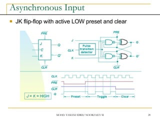
Asynchronous Input
SR input, D and JK is synchronous input. Where
data from input will be transferred to flip-flop
output only when edge triggered of clock pulse
Asynchronous Input free change condition from
pulse clock. Example: preset (PRE) and clear
(CLR) [or direct set (SD) and direct reset (RD)]
When PRE=HIGH, Q immediately HIGH
When CLR=HIGH, Q immediately LOW
Flip flop function as normal when both PRE and
CLR is LOW
28. MOHD. YAMANI IDRIS/ NOORZAILY MOHAMED NOOR 28
Asynchronous Input
JK flip-flop with active LOW preset and clear
29. MOHD. YAMANI IDRIS/ NOORZAILY MOHAMED NOOR 29
Master Slave Flip-flop
Master is activated when positive edge and
Slave is activated when clock negative edge
triggered
Master Slave Flip-flop