Downloaded 409 times


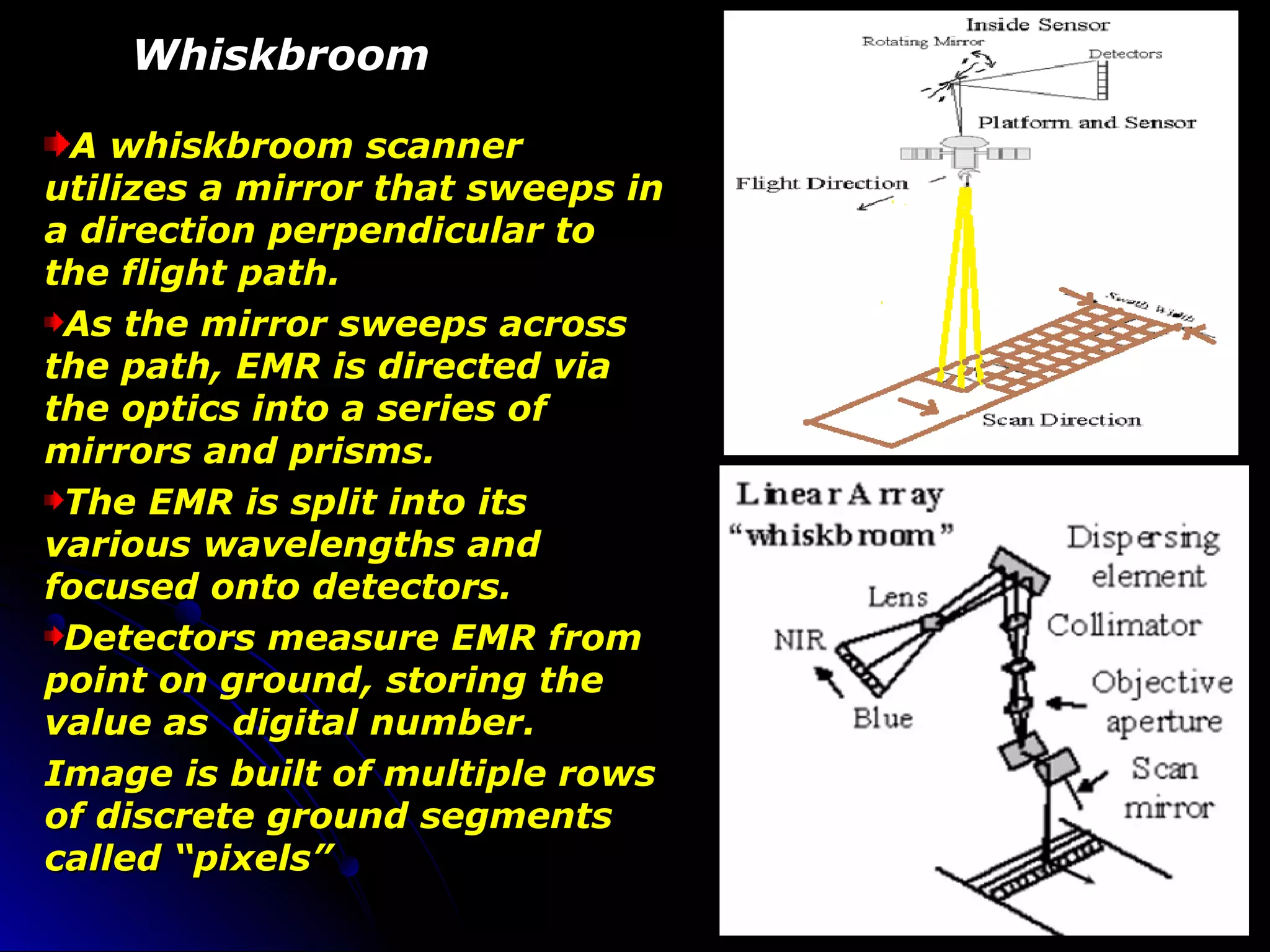


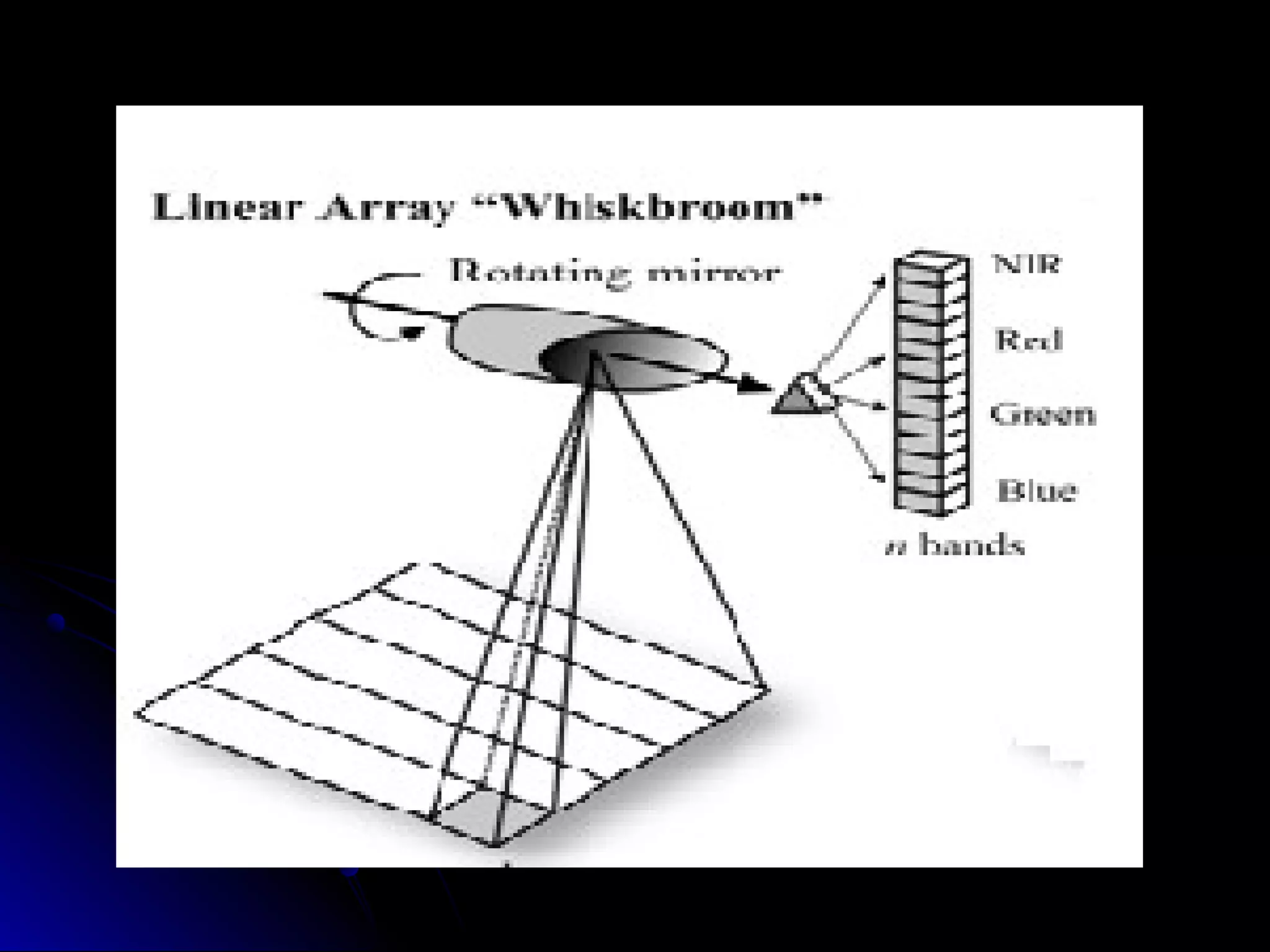

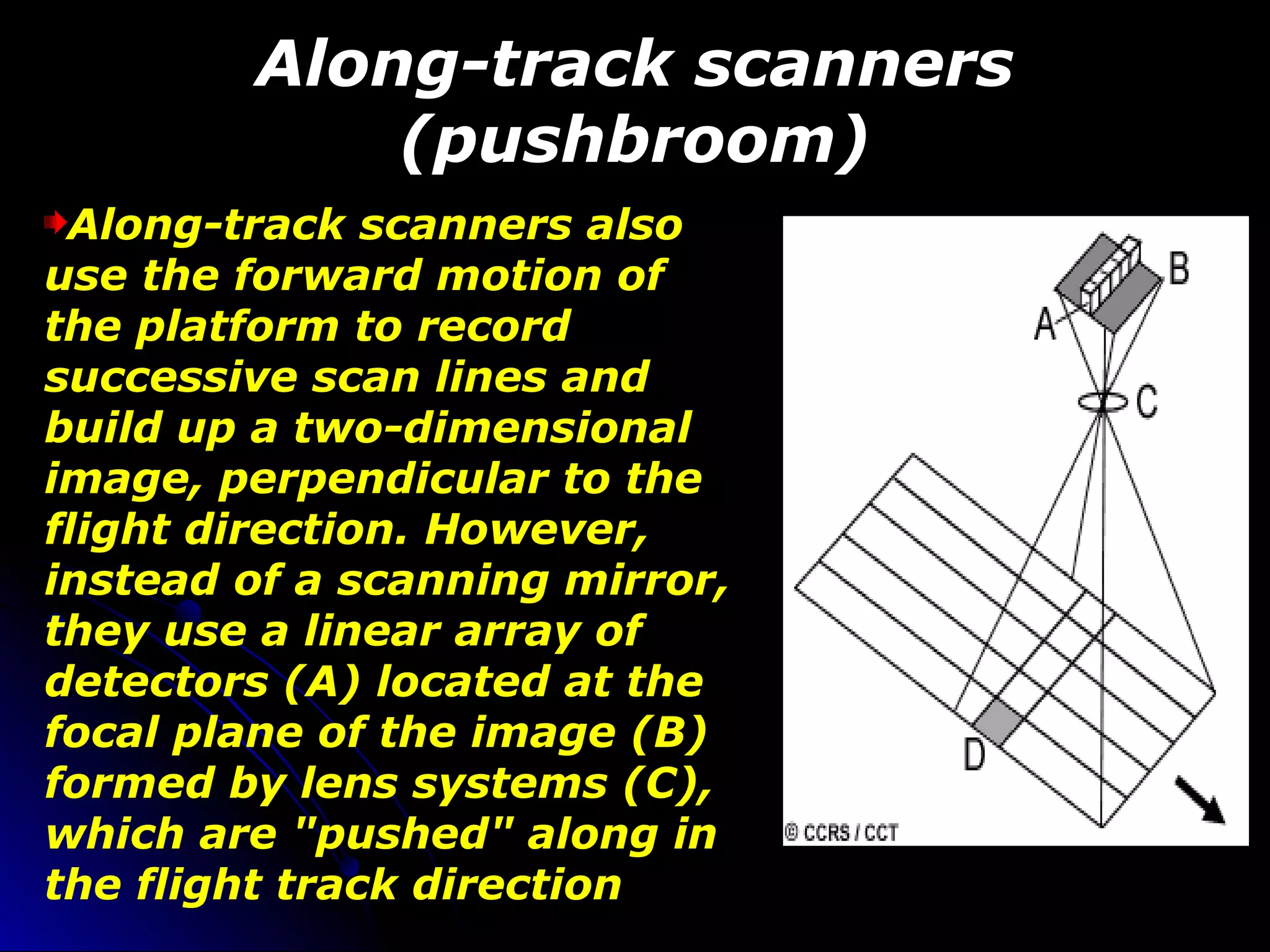
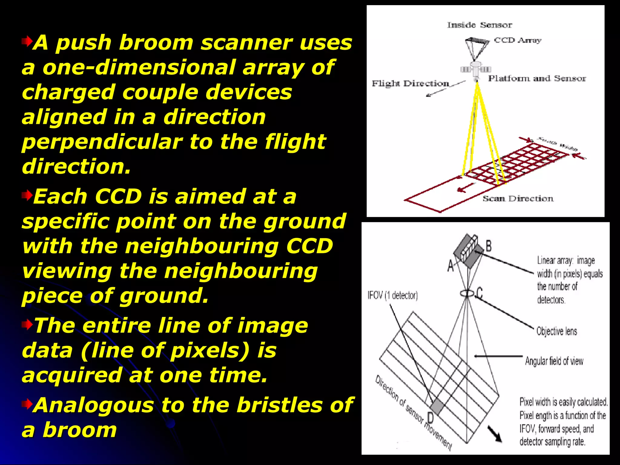


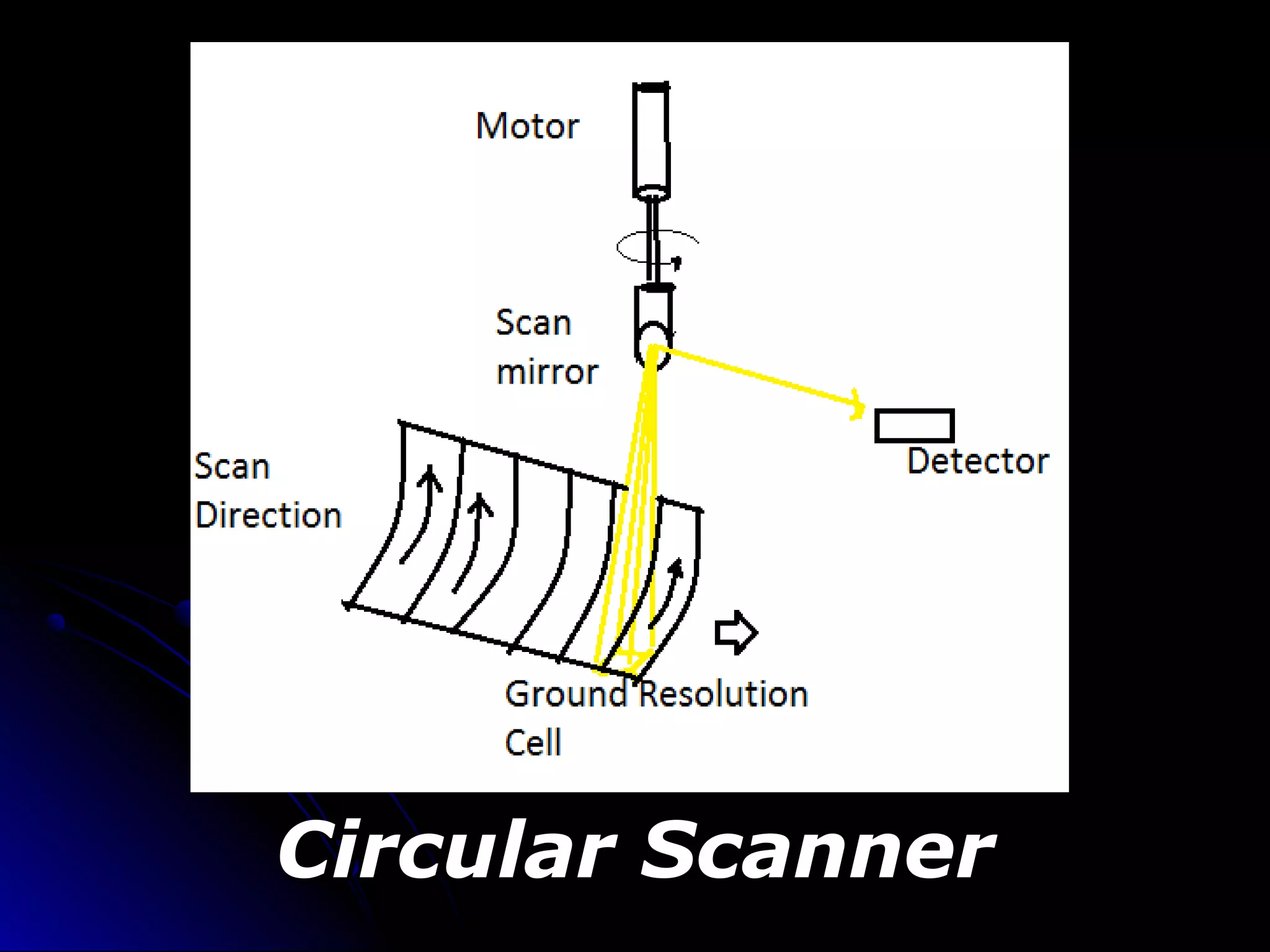


The document discusses different types of scanning systems used to collect remote sensing data. It describes whiskbroom scanners that use rotating mirrors to scan perpendicular to the flight path, building up images line-by-line. Pushbroom scanners use linear detector arrays that collect entire lines of pixels simultaneously as the sensor moves. Circular scanners employ rotating mirrors to scan in circular patterns, while side-scanning uses active radar to illuminate terrain to one side of the flight path. The characteristics of Landsat, SPOT, and sensor technologies are also overviewed.


