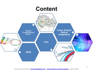
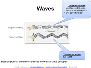
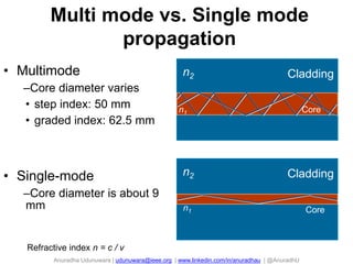
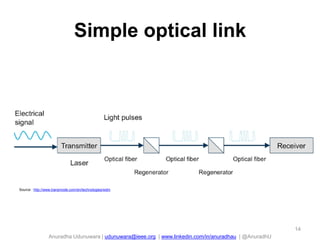
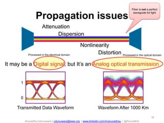
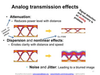
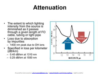
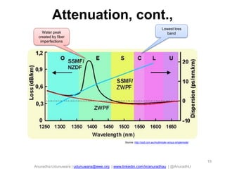
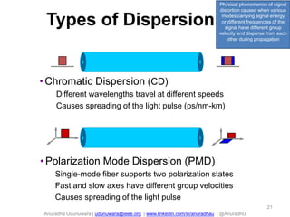
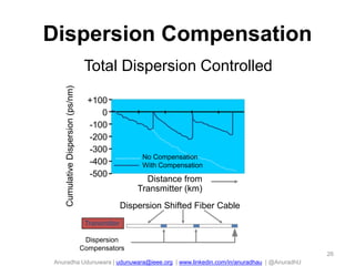
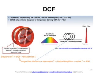
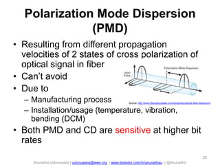
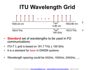
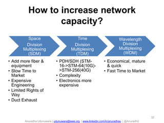
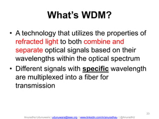
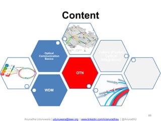
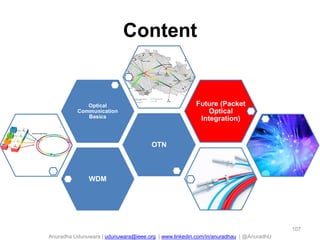
4. Anuradha Udunuwara | udunuwara@ieee.org | www.linkedin.com/in/anuradhau | @AnuradhU
Waves
4
Longitudinal wave
• Oscillates in the same
direction as propagation
• Ex:- Sound waves
Transverse waves
• Ex:- Light
Both longitudinal or transverse waves follow basic wave principles
5. Anuradha Udunuwara | udunuwara@ieee.org | www.linkedin.com/in/anuradhau | @AnuradhU
Terminology
5
: length of a wave in a
particular medium.
Common unit: nanometers
(nm), 10-9 m
f: the number of times that a wave is
produced within a particular time period.
Common unit: TeraHertz (Thz), 1012
cycles per second
c = f
c = velocity of light in a
vacuum = 3 x 10⁸ m/s
(constant)
f = frequency (Hz)
= wavelength (m)
f 1 /
6. Anuradha Udunuwara | udunuwara@ieee.org | www.linkedin.com/in/anuradhau | @AnuradhU
6
cannot see!
1. wavelength of these waves is too long for the human eye to detect
2. radio waves are not scattered as much as light waves by gas and dust, and can
penetrate clouds
850, 1310, 1550 nm
7. Anuradha Udunuwara | udunuwara@ieee.org | www.linkedin.com/in/anuradhau | @AnuradhU
dB vs. dBm
dB (Decibels)
• unit of level (relative
measure)
• Standard logarithmic unit for
the ratio of two quantities
• X dB is 10-X/10 in linear
dimension
• Ex:- 3 dB Attenuation = 10-0.3 =
0.501
• In optical fibres, the ratio is
power and represents loss
or gain
dBm (Decibels-milliwatt)
• absolute value
• used for output power
and receive sensitivity
• dBm : Decibel
referenced to a milliwatt
• X mW = 10log10(X) dBm
• Y dBm = 10Y/10 mW
• Ex:- 0 dBm = 1 mW,
17dBm = 50 mW
7
9. Anuradha Udunuwara | udunuwara@ieee.org | www.linkedin.com/in/anuradhau | @AnuradhU
Fiber
• Capacity
• Distance
The optical fiber cable in the foreground has the
equivalent capacity of the copper cable in the background
Source : http://www.igpolicysummit.org/uncategorized/copper-v-fiber-verizon-makes-a-change-following-sandys-devastation/
9
10. Anuradha Udunuwara | udunuwara@ieee.org | www.linkedin.com/in/anuradhau | @AnuradhU
CladdingCore
Coating
Fiber Geometry
• Core: carries the
light signals
• Cladding: keeps the light
in the core
• Coating: protects the glass
11. Anuradha Udunuwara | udunuwara@ieee.org | www.linkedin.com/in/anuradhau | @AnuradhU
q1
n2
n1
Cladding
q0 Core
Intensity Profile
Propagation in Fiber
• Light propagates by total internal reflections at the
core-cladding interface
• Total internal reflections are lossless
• Each allowed ray is a mode
12. Anuradha Udunuwara | udunuwara@ieee.org | www.linkedin.com/in/anuradhau | @AnuradhU
Single vs. multi mode
Source: http://osd.com.au/multimode-versus-singlemode/
Mode=Path of light
High Attenuation (3 dB/km)
High dispersion
Expensive today (because of less demand)
Attenuation = 0.22 dB/km (G.652 @ 1550nm)
No mode dispersion
12
13. Anuradha Udunuwara | udunuwara@ieee.org | www.linkedin.com/in/anuradhau | @AnuradhU
n2
n1
Cladding
Core
n2
n1
Cladding
Core
Multi mode vs. Single mode
propagation
• Multimode
–Core diameter varies
• step index: 50 mm
• graded index: 62.5 mm
• Single-mode
–Core diameter is about 9
mm
Refractive index n = c / v
15. Anuradha Udunuwara | udunuwara@ieee.org | www.linkedin.com/in/anuradhau | @AnuradhU
Are our senses analog or digital?
15
16. Anuradha Udunuwara | udunuwara@ieee.org | www.linkedin.com/in/anuradhau | @AnuradhU
Attenuation
Dispersion
Nonlinearity
Waveform After 1000 KmTransmitted Data Waveform
Distortion
It may be a Digital signal, but It’s an Analog optical transmission
Propagation issues
16
1
0
Fiber is not a perfect
waveguide for light
Processed in the electrical domain Processed in the optical domain
17. Anuradha Udunuwara | udunuwara@ieee.org | www.linkedin.com/in/anuradhau | @AnuradhU
Analog transmission effects
• Attenuation:
– Reduces power level with distance
• Dispersion and nonlinear effects:
– Erodes clarity with distance and speed
• Noise and Jitter: Leading to a blurred image
17
Ex:-FWM
18. Anuradha Udunuwara | udunuwara@ieee.org | www.linkedin.com/in/anuradhau | @AnuradhU
Attenuation
• The extent to which lighting
intensity from the source is
diminished as it passes
through a given length of FO
cable, tubing or light pipe
• Loss due to absorption
by impurities
– 1400 nm peak due to OH ions
• Specified in loss per kilometer
(dB/km)
– 0.40 dB/km at 1310 nm
– 0.25 dB/km at 1550 nm
1310
Window
1550
Window
19. Anuradha Udunuwara | udunuwara@ieee.org | www.linkedin.com/in/anuradhau | @AnuradhU
Attenuation, cont.,
Source: http://osd.com.au/multimode-versus-singlemode/
Water peak
created by fiber
imperfections
Lowest loss
band
19
20. Anuradha Udunuwara | udunuwara@ieee.org | www.linkedin.com/in/anuradhau | @AnuradhU
OA
(works fully in the optical domain)
Solution for Attenuation
Loss
Optical
Amplification
20
21. Anuradha Udunuwara | udunuwara@ieee.org | www.linkedin.com/in/anuradhau | @AnuradhU
• Polarization Mode Dispersion (PMD)
Single-mode fiber supports two polarization states
Fast and slow axes have different group velocities
Causes spreading of the light pulse
• Chromatic Dispersion (CD)
Different wavelengths travel at different speeds
Causes spreading of the light pulse (ps/nm-km)
Types of Dispersion
21
Physical phenomenon of signal
distortion caused when various
modes carrying signal energy
or different frequencies of the
signal have different group
velocity and disperse from each
other during propagation
22. Anuradha Udunuwara | udunuwara@ieee.org | www.linkedin.com/in/anuradhau | @AnuradhU
Chromatic dispersion
22
Source: http://www.bubblews.com/news/2058509-somewhere-over-the-rainbow
degrades the signal shape
color
Inter-symbol Interference (ISI)
leads to performance
impairments
Source : http://www.transmode.com/en/technologies/wdm
23. Anuradha Udunuwara | udunuwara@ieee.org | www.linkedin.com/in/anuradhau | @AnuradhU
60 Km SMF-28
4 Km SMF-28
10 Gbps
40 Gbps
Limitations From CD
t
t
• Dispersion causes pulse distortion
• Higher bit-rates and shorter pulses are less robust
to Chromatic Dispersion
• Limits "how fast“ and “how far”
23
24. Anuradha Udunuwara | udunuwara@ieee.org | www.linkedin.com/in/anuradhau | @AnuradhU
Combating CD
• Use DSF and NZDSF fibers
– G.653 & G.655
• Dispersion Compensating Fiber
(DCF/DCM)
• Transmitters with narrow spectral width
24
25. Anuradha Udunuwara | udunuwara@ieee.org | www.linkedin.com/in/anuradhau | @AnuradhU
DSF and NZDSF
Wavelength/nm
Dispersion
coefficient
1310 1550
17 ps/nm/km
4.5 ps/nm/km
G.652: widely used,
need DCF for high
rate transmission,
cheapest
G.655: little
dispersion to
avoid FWM,
expensive
G.653: Main
application:
submarine
25
26. Anuradha Udunuwara | udunuwara@ieee.org | www.linkedin.com/in/anuradhau | @AnuradhU
Dispersion Compensation
Transmitter
Dispersion
Compensators
Dispersion Shifted Fiber Cable
+100
0
-100
-200
-300
-400
-500
CumulativeDispersion(ps/nm) Total Dispersion Controlled
Distance from
Transmitter (km)
No Compensation
With Compensation
26
28. Anuradha Udunuwara | udunuwara@ieee.org | www.linkedin.com/in/anuradhau | @AnuradhU
Polarization Mode Dispersion
(PMD)
• Resulting from different propagation
velocities of 2 states of cross polarization of
optical signal in fiber
• Can’t avoid
• Due to
– Manufacturing process
– Installation/usage (temperature, vibration,
bending (DCM)
• Both PMD and CD are sensitive at higher bit
rates
Source: http://www.fiberoptics4sale.com/wordpress/optical-fiber-dispersion/
28
29. Anuradha Udunuwara | udunuwara@ieee.org | www.linkedin.com/in/anuradhau | @AnuradhU
Combating PMD
• Improved fibers
• Regeneration
– Light signal is detected & converted to an
electrical signal that is amplified, reshaped &
converted back to an optical signal
• Follow manufacturer’s recommended
installation techniques for the fiber cable
29
30. Anuradha Udunuwara | udunuwara@ieee.org | www.linkedin.com/in/anuradhau | @AnuradhU
ITU Wavelength Grid
• Standard set of wavelengths to be used in FO
communications
• ITU-T grid is based on 191.7 THz + 100 GHz
• It is a standard for laser in DWDM systems
• Wavelength spacing could be 50GHz, 100GHz, 200GHz, ….
1530.33 nm 1553.86 nm
0.80 nm
195.9 THz 193.0 THz
100 GHz
32. Anuradha Udunuwara | udunuwara@ieee.org | www.linkedin.com/in/anuradhau | @AnuradhU
How to increase network
capacity?
Space
Division
Multiplexing
(SDM)
• Add more fiber &
equipment
• Slow Time to
Market
• Expensive
Engineering
• Limited Rights of
Way
• Duct Exhaust
Time
Division
Multiplexing
(TDM)
• PDH/SDH (STM-
16->STM-64(10G)-
>STM-256(40G)
• Complexity
• Electronics more
expensive
Wavelength
Division
Multiplexing
(WDM)
• Economical, mature
& quick
• Fast Time to Market
32
33. Anuradha Udunuwara | udunuwara@ieee.org | www.linkedin.com/in/anuradhau | @AnuradhU
What’s WDM?
• A technology that utilizes the properties of
refracted light to both combine and
separate optical signals based on their
wavelengths within the optical spectrum
• Different signals with specific wavelength
are multiplexed into a fiber for
transmission
33
34. Anuradha Udunuwara | udunuwara@ieee.org | www.linkedin.com/in/anuradhau | @AnuradhU
What’s WDM? , Contd.,
Gas Station
Free Way
Petrol Car
Freeway : Fiber
Petrol Car : Supervisory Signal
Gas Station : Optical relay
Gray Car : Client Service
Colored Car : Service in different channels (wavelength)
Driveway : Optical wavelength 34
35. Anuradha Udunuwara | udunuwara@ieee.org | www.linkedin.com/in/anuradhau | @AnuradhU
TDM Vs. WDM
SONET
35
• Takes sync and async signals &
multiplexes them to a single higher
optical bit rate
• 4 STM-1 channels in STM-4
• 4 STM-4 channels in STM-16
• 16 STM-4 channels in STM-64
• E/O or O/E/O conversion
• Single wavelength per fiber
• Takes multiple optical signals and multiplexes
onto a single fiber
• No signal format conversion
• Multiple wavelengths per fiber
37. Anuradha Udunuwara | udunuwara@ieee.org | www.linkedin.com/in/anuradhau | @AnuradhU
WDM History
• Early WDM (late 80s)
– Two widely separated wavelengths (1310, 1550nm)
• “Second generation” WDM (early 90s)
– Two to eight channels in 1550 nm window
– 400+ GHz spacing
• DWDM systems (mid 90s)
– 16 to 40 channels in 1550 nm window
– 100 to 200 GHz spacing
• Next generation DWDM systems
– 64 to 160 channels in 1550 nm window
– 50 and 25 GHz spacing
37
38. Anuradha Udunuwara | udunuwara@ieee.org | www.linkedin.com/in/anuradhau | @AnuradhU
Why WDM?
• Capacity upgrade of existing fiber
networks (without adding fibers)
• Transparency: Each optical channel can
carry any transmission format (different
asynchronous bit rates, analog or digital)
• Scalability: Buy and install equipment for
additional demand as needed
• Wavelength routing and switching:
Wavelength is used as another dimension
to time and space
38
39. Anuradha Udunuwara | udunuwara@ieee.org | www.linkedin.com/in/anuradhau | @AnuradhU
WDM principle elements
• Allow traffic to enter and leave the optical network
– Transponder
• Signal/wavelength converter
– Muxponder
• Combines several client signals into one line signal
• Multiplex wavelengths
– Optical multiplexer (MUX) and de-multiplexer
• Send wavelengths in different directions
– ROADM
• Optical Amplifier (Amp)
• Supervisory channel
• Optical Source
39
42. Anuradha Udunuwara | udunuwara@ieee.org | www.linkedin.com/in/anuradhau | @AnuradhU
System structure
OTU1
OTUn
OTU2
OTU1
OTUn
OTU2
OSCOSCOSC
OLA
Optical Transponder
Unit: Access the client
services & convert the
wavelength compiled with
ITU standard
Optical Multiplexer Unit:
Multiplex several services
with different wavelength
into one main path signal
OA
Optical Amplifier:
Amplifies the optical
signal
Optical Supervisory
Channel: Terminate &
Re-generation. Not
amplification.
Optical De-multiplexer
Unit: De-multiplex one
main path signal into
several individual signals
Optical Line
Amplifier
1
2
n
nm nm
1,2..n
1
2
n
P
A
A P
A
A
P
A
P
Active
Passive
OA
A
1,2..n
P
O
M
U
P
O
D
U
42
P
43. Anuradha Udunuwara | udunuwara@ieee.org | www.linkedin.com/in/anuradhau | @AnuradhU
Loss
• Passive => Loss (power reduction)
– Ex:- Input power to the MUX 0 dB. Output power from
the MUX -6 dB. Therefore the loss is 6 dB
• Loss can be due to splicing, distance, bending,
aging, connectors
43
Source: http://www.thefoa.org/tech/lossbudg.htm
44. Anuradha Udunuwara | udunuwara@ieee.org | www.linkedin.com/in/anuradhau | @AnuradhU
Definition of the line side
44
Source : http://www.transmode.com/en/technologies/wdm
45. Anuradha Udunuwara | udunuwara@ieee.org | www.linkedin.com/in/anuradhau | @AnuradhU
OTU- Optical Transponder Unit
O
OE
ENon-color
(Not defined by ITU-T)
Ex:-
1310 nm short reach SMF
1550 nm long reach SMF
850 nm MMF
Can’t use these in WDM
without OTU
Color
(Defined by ITU-T)
Ex:-
1: 1550.51 nm
2 :1551.23 nm
45
SMF-Single Mode Fiber
MMF-Multi Mode Fiber
Optical to
Electrical
conversion
Electrical to
Optical
conversion
Wavelength conversion
46. Anuradha Udunuwara | udunuwara@ieee.org | www.linkedin.com/in/anuradhau | @AnuradhU
Uni Versus Bi-directional WDM
WDM systems can be implemented in two different ways
Bi -directional
5
6
7
8
Fiber
1
2
3
4
Uni -directional
1
3
5
7
Fiber
Fiber
1
3
5
7
2
4
6
8
2
4
6
8
• Uni-directional:
wavelengths for one direction travel
within one fiber
two fibers needed for full-duplex
system
• Bi-directional:
a group of wavelengths for each
direction
single fiber operation for full-duplex
system
46
47. Anuradha Udunuwara | udunuwara@ieee.org | www.linkedin.com/in/anuradhau | @AnuradhU
WDM network topologies
• Point to Point
• Ring
• Mesh
Cost
Complexity
Reliability
47
49. Anuradha Udunuwara | udunuwara@ieee.org | www.linkedin.com/in/anuradhau | @AnuradhU
CWDM vs. DWDM, cont.,
Types CWDM DWDM
Channel spacing (Grid) 20 nm (fixed) 100 GHz/ 50 GHz/ 25 GHz
Band 1311~1611 nm
(All bands)
C-band:
1529nm~1561nm
L-band:
1570nm~1603nm
Capacity (max) 18 x 10 Gbps 192 x 10 Gbps
Laser Un-cooled Laser Cooled Laser
Cost 70% 100%
Application 100 km (max) 5000 km
49
Since f 1 / ,
channel
spacing can
be denotes as
both distance
and frequency
As CWDM
works in all 5
bands,
amplification is
NOT possible
51. Anuradha Udunuwara | udunuwara@ieee.org | www.linkedin.com/in/anuradhau | @AnuradhU
SDH/SONET vs. WDM
51
All traffic signals are regenerated and
switched, making them available for
add and drop
Only selected signals (wavelengths) are
available for add and drop, the rest are
“glassed through”.
Source : http://www.transmode.com/en/technologies/wdm
• Signals are regenerated at each node- the equivalent
uninterrupted “wire” stretches only between 2 nodes
• A new power budget is calculated for each hop between 2
adjacent node
• Light paths in a WDM network are e2e connections, &
should be considered as the equivalents of uninterrupted
“wires”, stretching from one point in the network to
another while passing one or several nodes
• Optical transmission characteristics for a wavelength has
to be calculated for the complete distance the light path
traverse
52. Anuradha Udunuwara | udunuwara@ieee.org | www.linkedin.com/in/anuradhau | @AnuradhU
Modulation
• DAC?
– medium/channel is band pass (Ex:- light), and/or
– multiple users need to share the medium
• Analog signal
– Typically sinusoidal
• Amplitude->ASK
• Frequency->FSK
• Phase->PSK
• Digital signal
– 1
– 0
52
QAM
Susceptible
to noise
56. Anuradha Udunuwara | udunuwara@ieee.org | www.linkedin.com/in/anuradhau | @AnuradhU
Comparison of optical modulators
Types Direct Electro-
Absorption
External
Mach-
Zehnder
External
Coherent
Max.
dispersion
tolerance
(ps/nm)
1200-4000 7200-12800 >12800 40000
Cost moderate expensive Very
expensive
Very
expensive
Wavelength
stability
good better best best
56
57. Anuradha Udunuwara | udunuwara@ieee.org | www.linkedin.com/in/anuradhau | @AnuradhU
57
Direct
Detection
(optical
power
measuring
process)
Coherent
detection
(process is
sensitive to
the
amplitude,
frequency
and phase
(Ex:- 16QAM,
64QAM for
100G and
above)
58. Anuradha Udunuwara | udunuwara@ieee.org | www.linkedin.com/in/anuradhau | @AnuradhU
Tx and Rx
Optical transmitter
• Semiconductor
– LED
– Laser
Optical receiver
• Photodetector
58
Source : http://www.transmode.com/en/technologies/wdm
Produces a coherent
(light of one wavelength
with all the light waves
being in same phase)
light
Coherent light is a prerequisite for long reach over fiber
59. Anuradha Udunuwara | udunuwara@ieee.org | www.linkedin.com/in/anuradhau | @AnuradhU
The Big Leap: 10G to 100G Coherent
59Source: 2nd Annual WDM & Next Generation Optical Networking APAC 2014
Hard Decision FEC: for
every input and output
signal a hard decision is
made whether it
corresponds to a one or a
zero bit
Soft Decision
FEC: process
analog signals,
allowing much
higher error-
correction
performance
Dual
Polarization
62. Anuradha Udunuwara | udunuwara@ieee.org | www.linkedin.com/in/anuradhau | @AnuradhU
• Compensates the loss
• Any analog signal system has noise. Optical signal is also
analog
• More Amps-> more accumulated noise (N)->S/N->BIR
– Amp keeps Signal (S) constant.
• Solution: re-generation (electrical domain: OEO regeneration)
• Amplification and regeneration gives unlimited distance,
theoretically
– Ex:- 1500 km if the link has FEC
• Optical Signal to Noise Ration (OSNR) = Ratio of optical
signal power to noise power for the receiver
62
Pout = GPinPin
G
63. Anuradha Udunuwara | udunuwara@ieee.org | www.linkedin.com/in/anuradhau | @AnuradhU
Amplifier types
• EDFA - Erbium Doped Fiber Amplifier
– Widely used
– Only applicable for wavelengths in the C-band used by
DWDM
• RFA - Raman Fiber Amplifier
– Uses non-linearity effect
– Uses high power class 4 laser
• Use APC (Angular Physical Contact) connectors instead of PC
– Ex:-LC/APC (Lucent Connector), SC/APC, FC/APC
– 20 km distance
• Need to maintain splice loss <0.1dB within 1st 10 km and <0.2dB
within next 10 km
– Low noise
– Low gain efficiency (10~12 dB)
63
65. Anuradha Udunuwara | udunuwara@ieee.org | www.linkedin.com/in/anuradhau | @AnuradhU
Optical Multiplexer and de-
multiplexer
• TFF - Thin Film Filter
– when no. of channels<16
• AWG - Arrayed Waveguide Grating
– when no. of channels>=16
– expensive
65
66. Anuradha Udunuwara | udunuwara@ieee.org | www.linkedin.com/in/anuradhau | @AnuradhU
TFF
Source: http://www.fiberoptics4sale.com/wordpress/what-is-multilayer-dielectric-thin-film-filter/
0.1 dB loss. Therefore max. of 16
channels
Has the
lowest power
66
67. Anuradha Udunuwara | udunuwara@ieee.org | www.linkedin.com/in/anuradhau | @AnuradhU
AWG
Source: http://docstore.mik.ua/univercd/cc/td/doc/product/mels/cm1500/dwdm/dwdm_ovr.htm
All have the same
power
67
69. Anuradha Udunuwara | udunuwara@ieee.org | www.linkedin.com/in/anuradhau | @AnuradhU
Supervisory technologies
• OSC - Optical Supervisory Channel
– Often used in backbone systems
– Uses OTN (G.709) framing (similar to SDH)
– Costly
• ESC - Electrical Supervisory Channel
– Often used in metropolitan systems
– OTU is mandatory at every site
• OLA sites don’t have OTU. Therefore can’t mange
OLAs with ESC
69
70. Anuradha Udunuwara | udunuwara@ieee.org | www.linkedin.com/in/anuradhau | @AnuradhU
70
ADM OADM ROADM
function in the
traditional SONET/
SDH networks
• is a device used in
photonic domain
under WDM
systems for
multiplexing
and routing
different channels
of light into or out
of a single mode
fiber
• best solution for a
small & static
optical network
• OADM with
remotely
reconfigurable
optical switches in
the middle stage
• Enables more
automation,
reducing the risk
for manual errors
• best solution for a
larger optical
network
71. Anuradha Udunuwara | udunuwara@ieee.org | www.linkedin.com/in/anuradhau | @AnuradhU
OADM
OADMs allow flexible add/drop of channels
Drop
Channel
Add
Channel
Drop &
Insert
71
72. Anuradha Udunuwara | udunuwara@ieee.org | www.linkedin.com/in/anuradhau | @AnuradhU
Key attributes of ROADM Module
• Fully Flexible, Remotely
Reconfigurable Optical
Add Drop
• Automatic power
equalization on inputs,
outputs, adds, drops
• Optical Power Monitoring
(OPM) of all channels
Key benefits of ROADM Module
• Elimination of the OEO
“Pass-through” tax
• Scalable Bandwidth (Start
with 1, grow by 1 )
• Single Wavelength
Granularity – No stranded
bandwidth
• Fully Automated Optical
Layer
72Source: 2nd Annual WDM & Next Generation Optical Networking APAC 2014
73. Anuradha Udunuwara | udunuwara@ieee.org | www.linkedin.com/in/anuradhau | @AnuradhU
Static Networks Based on Fixed-
Wavelength Filters
• Topology and capacity/node
determined at time of network design
– Traffic projections based upon best
estimates at the time
– Not always cost effective to
“overbuild” the system
• Can lead to premature system
exhaust
– Expected system lifetime: 5-10 yrs
– Traffic projections not accurate
leading to premature system exhaust
• Insufficient ’s available to hot spots
• Unlit ’s to cold spots cannot be utilized
– Topology is inconsistent for emerging
applications
• Telephony, SAN, Enterprise, VoD
73
Physical WDM Ring
Source: 2nd Annual WDM & Next Generation Optical Networking APAC 2014
74. Anuradha Udunuwara | udunuwara@ieee.org | www.linkedin.com/in/anuradhau | @AnuradhU
ROADMs Enable Any-Node-to-
Any-Node Topologies
• Provision
wavelengths
independently
between nodes
• No blocking
extends system
life to capacity
limitation
– Relieves need for
accurate traffic
growth
forecasting
74
Physical WDM Ring
Source: 2nd Annual WDM & Next Generation Optical Networking APAC 2014
75. Anuradha Udunuwara | udunuwara@ieee.org | www.linkedin.com/in/anuradhau | @AnuradhU
ROADM Generations
• 1st generation: Wavelengths Blocker
based ROADMs
– 2 degree nodes only
– 100 GHz channel spacing
– Add/Drop only
– Neither colorless nor directionless
• 2nd generation
– 2 degree nodes and very limited multi
degree functionality
– 100 GHz channel spacing
– Add/Drop only
– Neither colorless nor directionless node
support
• 3rd generation: WSS 1:N based
ROADMs
– Multi degree node support
– 50 GHz and 100 GHz channel spacing
– Colorless and directionless node
support
• 3rd + generation
– Multi degree node support
– Flexible channel spacing
– Future proof on
• Colorless and directionless node support
• Contentionless node support
75Source: 2nd Annual WDM & Next Generation Optical Networking APAC 2014
76. Anuradha Udunuwara | udunuwara@ieee.org | www.linkedin.com/in/anuradhau | @AnuradhU
2 degree ROADM
76
No. of
inputs
Source : http://www.transmode.com/en/technologies/wdm
1 MUX
per
direction
1 MUX
per
direction
Specific
MUX port
77. Anuradha Udunuwara | udunuwara@ieee.org | www.linkedin.com/in/anuradhau | @AnuradhU
Good features to have on a WSS
system
77
• Colorless
• Directionless
• Contentionless
78. Anuradha Udunuwara | udunuwara@ieee.org | www.linkedin.com/in/anuradhau | @AnuradhU
Colorless 2 degree ROADM
78
Source : http://www.transmode.com/en/technologies/wdm
Any
connected to
any MUX
port
1 MUX
per
direction
1 MUX
per
direction
79. Anuradha Udunuwara | udunuwara@ieee.org | www.linkedin.com/in/anuradhau | @AnuradhU
Directionless 2 degree ROADM
79
can be made
colorless by
combining with traffic
units having tunable
transceivers
Source : http://www.transmode.com/en/technologies/wdm
Share
MUX
between
directions
80. Anuradha Udunuwara | udunuwara@ieee.org | www.linkedin.com/in/anuradhau | @AnuradhU
Directionless and contentionless
2 degree ROADM
80
can be made
colorless by
combining with traffic
units having tunable
transceivers
Source : http://www.transmode.com/en/technologies/wdm
1 MUX
per
direction
Multiples of same can
be add/drop to same MUX
86. Anuradha Udunuwara | udunuwara@ieee.org | www.linkedin.com/in/anuradhau | @AnuradhU
WSON
86
WDM
fiber link
OXC
(GMPLS)
Source: Wikipedia
87. Anuradha Udunuwara | udunuwara@ieee.org | www.linkedin.com/in/anuradhau | @AnuradhU
Generalized Multi-Protocol Label
Switching (GMPLS)
• The optical layer is connection oriented (circuit switched), Light paths are
easy to be established
• Light paths can be seen as LSPs between ingress and egress OXCs.
• Multiprotocol Lambda Switching (MPλS) was defined as a control plane for
optical networks
• MPLS and MPλS were then unified and called GMPLS (RFC 3945)
• Extends MPLS to provide the control plane (signaling and routing) for
devises that switch in any of these domains: packet, time, wavelength and
fiber
• GMPLS starting point is based on the IP view of the transport plane: one
physical layer
– Fibers are the reference points
– Equipment are black boxes identified by switching capabilities
– Topology and link state information distributed to all equipment independent of
network layer the equipment operates on (“peering”)
• GMPLS is a tool box which can be used to support ASON’s view of the
transport plane
87
89. Anuradha Udunuwara | udunuwara@ieee.org | www.linkedin.com/in/anuradhau | @AnuradhU
What is “OTN”?
• As per ITU-T, it’s G.709 standard
– a.k.a Digital Wrapper (DW)
– a.k.a Optical Transport Hierarchy (OTH) standard
• OTN could mean;
– OTN wrapper capability
– OTN switching capability
• In the industry/telco field?
– OTN
– POT (Packet Optical Transport)
• packet (MPLS-TP?)+ TDM (SDH/PDH) + WDM + ROADM
– Optical Packet Transport layer
89
90. Anuradha Udunuwara | udunuwara@ieee.org | www.linkedin.com/in/anuradhau | @AnuradhU
OTN aim
• Combine the
– Benefits of SONET/SDH (OAM&P)
• Monitoring a connection e2e over multiple
transport segments
– Bandwidth expandability of DWDM
• Designed to transport both
– Packet mode traffic : IP and Ethernet
– Legacy SDH/SONET traffic
• Includes FEC
90
91. Anuradha Udunuwara | udunuwara@ieee.org | www.linkedin.com/in/anuradhau | @AnuradhU
Main functionality provided by
an OTN
• Transparent transport of different optical
clients
• Interconnection of different administrative
domains
• Optical channel networking and protection
• Performance monitoring and alarm
supervision
• Network management
91
92. Anuradha Udunuwara | udunuwara@ieee.org | www.linkedin.com/in/anuradhau | @AnuradhU
STM-1 frame is the basic transmission format for SDH
92Source : http://www.transmode.com/en/technologies/wdm
93. Anuradha Udunuwara | udunuwara@ieee.org | www.linkedin.com/in/anuradhau | @AnuradhU
SONET & SDH multiplexing
hierarchies
93
Source : http://www.transmode.com/en/technologies/wdm
All the clocks in the SDH/SONET network are perfectly
synchronized to a single master clock. This allows lower
speed signals to be added/dropped from the SDH/SONET
stream without de-multiplexing the entire stream into its
individual components
94. Anuradha Udunuwara | udunuwara@ieee.org | www.linkedin.com/in/anuradhau | @AnuradhU
OTN signal structure and terminology (Ex:-)
94
Carrier Ethernet frame
is carried as the payload of an
Optical Channel Payload Unit
(OPU)
Source : http://www.transmode.com/en/technologies/wdm
96. Anuradha Udunuwara | udunuwara@ieee.org | www.linkedin.com/in/anuradhau | @AnuradhU
OTN vs. SDH/SONET line rates
96
Source : http://www.transmode.com/en/technologies/wdm
97. Anuradha Udunuwara | udunuwara@ieee.org | www.linkedin.com/in/anuradhau | @AnuradhU
Pre-OTN WDM Vs. OTN
Pre-OTN WDM
• simple transport
• Bandwidth
multiplication by
means of WDM
transport
• Point-to-point
application that can
transport STM-N/OC-
N as a service
OTN
• networking – solution
• Management enabler
of WDM network
• First transmission
technology in which
each stakeholder gets
its own (ODUk)
connection monitoring
97
98. Anuradha Udunuwara | udunuwara@ieee.org | www.linkedin.com/in/anuradhau | @AnuradhU
OTN switching
98
• Prime advantage: sub-lambda grooming at intermediate
sites.
• Industry trend(both suppliers and operators): Start
WITHOUT OTN switching and go for OTN switching in
the future if all the lambdas run out/close to run out (aka
Wave-length blocking).
• This requires that you select a vendor who's capable of
OTN switching but you need NOT purchase OTN
switching components (cards) on day one.
• You do NOT need OTN switching to achieve mesh
protection. What is then required is ASON/GMPLS.
99. Anuradha Udunuwara | udunuwara@ieee.org | www.linkedin.com/in/anuradhau | @AnuradhU
OTN networking efficiency:
virtual wavelengths
• Flexible granularity options to maximize services
and revenue per wavelength
99
Source: 2nd Annual WDM & Next Generation Optical Networking APAC 2014
100. Anuradha Udunuwara | udunuwara@ieee.org | www.linkedin.com/in/anuradhau | @AnuradhU
All-Optical (without digital switching)
• “Services over
wavelengths” - static
• Inefficient
• Optical-only switching
• No digital switching &
reconfiguration
• Patch panel & truck-roll
re-grooming
100
Source: 2nd Annual WDM & Next Generation Optical Networking APAC 2014
103. Anuradha Udunuwara | udunuwara@ieee.org | www.linkedin.com/in/anuradhau | @AnuradhU
Available options
103
1. FOADM
2. ROADM
3. Tunable ROADM (TROADM)
4. FOADM with ASON/GMPLS control plane
5. ROADM with ASON/GMPLS control plane
6. TROADM with ASON/GMPLS control plane
7. FOADM with ASON/GMPLS control plane and OTN switching
8. ROADM with ASON/GMPLS control plane and OTN switching
9. TROADM with ASON/GMPLS control plane and OTN switching
Note: All options need to support OTN wrapper
Costincreases
104. Anuradha Udunuwara | udunuwara@ieee.org | www.linkedin.com/in/anuradhau | @AnuradhU
3 CAPEX components
104
Cost of adding OTN switching capability vs. loosing sub-lambda
grooming at intermediate sites need to be properly analyzed
based on your current and future traffic matrix.
CAPEX I
When you want
to do sub-lambda
grooming at
intermediate
sites, you'll have
to have OTN
switching
CAPEX II
When you have OTN
switching, the earlier Point-to-
Point lambda passed through
several intermediate nodes at
the optical domain (OOO) now
need to go to electrical domain
to do grooming (OEO) making
it multi-segment. This requires
several OTN ports . However,
you use only one lambda.
Some call the latter as Layer
1-ASON and former as Layer
0-ASON.
CAPEX III
If you do not do sub-
lambda grooming at
the intermediate site,
you will have to have a
separate lambda at the
intermediate site,
though the traffic goes
to the same
destination.
105. Anuradha Udunuwara | udunuwara@ieee.org | www.linkedin.com/in/anuradhau | @AnuradhU
Optical Backbone Networks
- evolution scenarios
short term medium term long term
Introduction of
reconfigurable WDM
networks (ROADM)
GFP, enhanced
SDH/SONET
technologies and
OTN
addition of a
control plane, either
ASON or GMPLS
based.
105
110. Anuradha Udunuwara | udunuwara@ieee.org | www.linkedin.com/in/anuradhau | @AnuradhU
Alternative implementations of IP over WDM
110
Packet over SONET with
HDLC framing
Packet over SONET with
GFP framing
Ethernet framing
Source : http://www.transmode.com/en/technologies/wdm
111. Anuradha Udunuwara | udunuwara@ieee.org | www.linkedin.com/in/anuradhau | @AnuradhU
Future of transport & switching
111
Source: http://www.transmode.com/en/technologies/wdm and Infonetics Research