


![CE Market
Services Revenue : $5B (2012) to over $11B (2017) [Insight Research]
Equipment Revenue: $31.7B (2011) to $42B (2016) [Infonetics]
CE Equipment spend: $186 billion over next 5 years!
(c) Anuradha Udunuwara](https://image.slidesharecdn.com/carreirethernet-130221023837-phpapp02/85/Carrier-Ethernet-49-320.jpg)


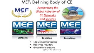


![Reference
[1] MEF ( http://metroethernetforum.org )
[2] Ethernet Academy
(http://www.ethernetacademy.net/ )
(c) Anuradha Udunuwara](https://image.slidesharecdn.com/carreirethernet-130221023837-phpapp02/85/Carrier-Ethernet-111-320.jpg)

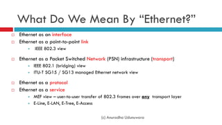
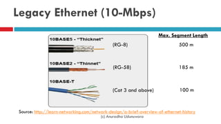
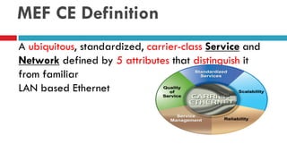
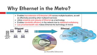
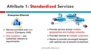
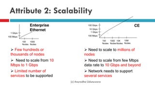
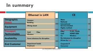
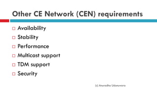
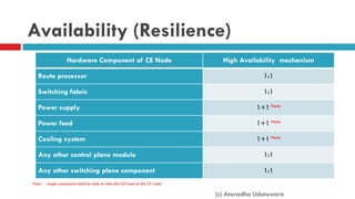
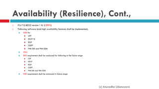
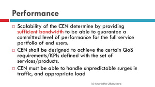
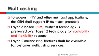
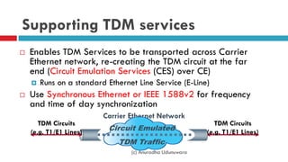
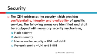
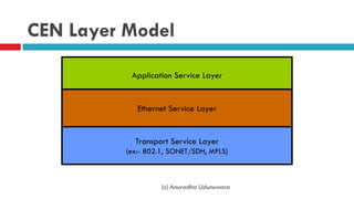
The document discusses Carrier Ethernet and provides definitions and background. It defines Ethernet and discusses its history and standards development. It then defines Carrier Ethernet, explaining that it provides standardized, carrier-class Ethernet services on a large scale with attributes like scalability, reliability, service management and quality of service. The document outlines requirements for Carrier Ethernet networks including availability, stability, performance, multicast and TDM support, and security.


![5G Explained! A High Level Overview [Introduction]](https://cdn.slidesharecdn.com/ss_thumbnails/5gexplainedahighleveloverview-260119165306-cc137a3e-thumbnail.jpg?width=640&height=640&fit=bounds)


