This document provides an overview of fiber optics, including:
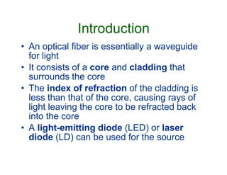
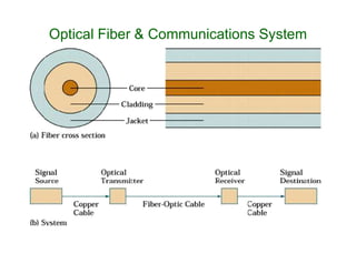
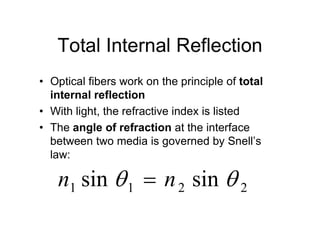
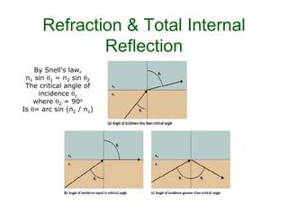
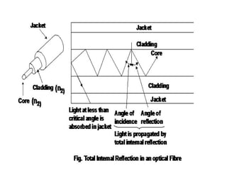
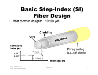
1. The basic principle of fiber optics is total internal reflection which guides light through the fiber core due to the core having a higher refractive index than the cladding.
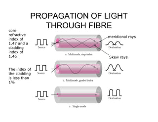
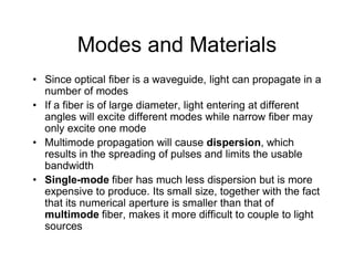
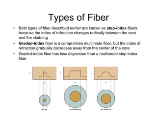
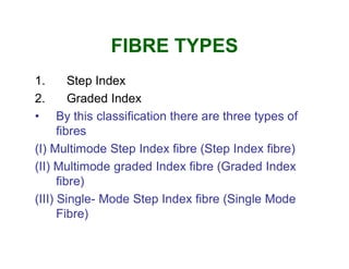
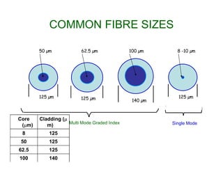
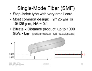
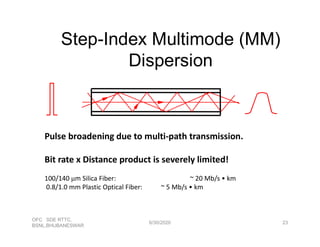
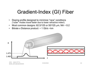
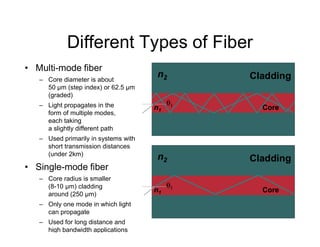
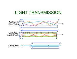
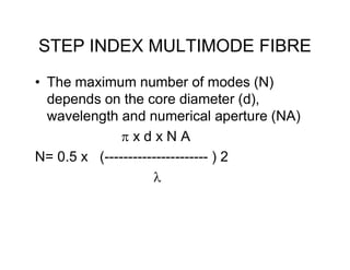
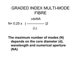
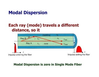
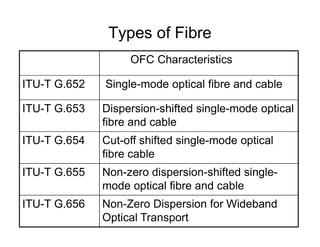
2. There are three main types of optical fibers - multimode step index, multimode graded index, and single mode fibers. Multimode fibers have larger cores and support multiple propagation modes while single mode fibers only support one mode.
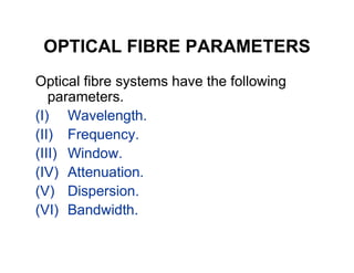
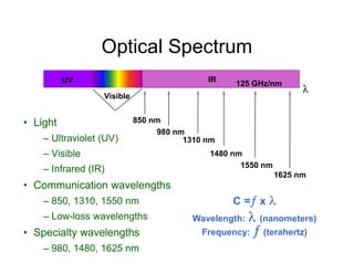
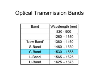
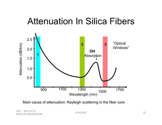
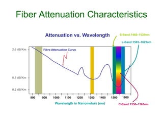
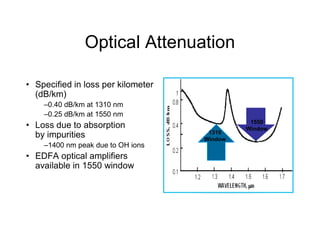
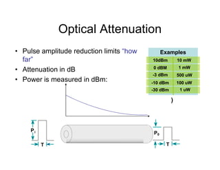
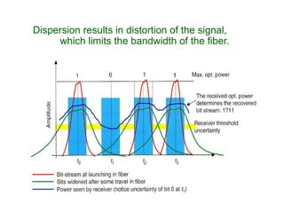
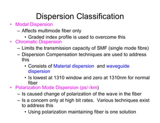
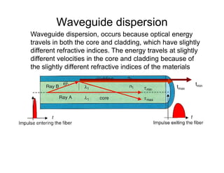
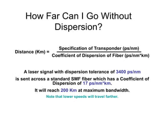
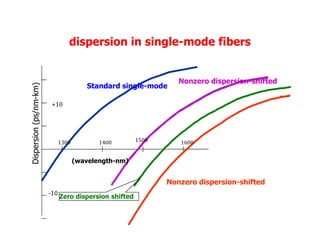
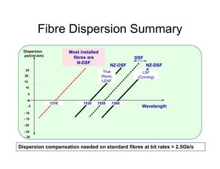
3. Key factors that determine fiber performance include attenuation, bandwidth, and dispersion. Attenuation and wavelength windows are material properties while dispersion depends on the fiber's construction and number of propagation modes.