Downloaded 4,102 times


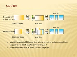
![OTM-N.M CONTAINMENT RELATIONSHIPS
“n” represents the maximum number of wavelengths that can be supported at the lowest bit rate
supported by the wavelengths. “m” equals 1, 2, 3, 12, 23, or 123.
OTS_OH, OMS_OH, OCh_OH and COMMS OH information fields are contained in the OOS.
The optical supervisory channel (OSC) is used to transmit OOSs.
Page11
OCCp OCCp OCCp
OCh payload
ODUk FECOH
OPUkOH
Client signal
OPUk payloadOHOPUk
ODUk
OTUk[V]
OCh
OCG-n.m
OTM-n.m OTSn OH
OMSn OH
OCCo
OChOH
OCCo
OCCo
OMU-n.m
Non-associatedOH
OOS
Common
management
OH
OTM-n.m
OTM overhead signal (OOS)
l 2
l 1
l n
l OSC](https://image.slidesharecdn.com/jc1qlvxvttiome720aj3-140610151857-phpapp01/85/OTN-for-Beginners-11-320.jpg)
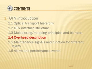
![OTM-NR.M CONTAINMENT RELATIONSHIPS
Fixed channel spacing, irrelevant to the signal rate
1 < n ≤ 16; m = 1, 2, 3, 12, 23, or 123
Without optical supervisory channels
Page12
OCCp OCCp OCCp
OCh payload
ODUk FECOH
OPUkOH
Client signal
OPUk payloadOHOPUk
ODUk
OTUk[V]
OChr
OCG-nr.m
OTM-nr.m
OTM-16r.m
l 2
l 1
l 16](https://image.slidesharecdn.com/jc1qlvxvttiome720aj3-140610151857-phpapp01/85/OTN-for-Beginners-12-320.jpg)
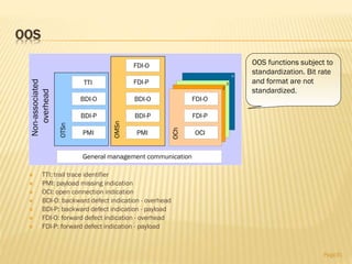
![OTM-0.M CONTAINMENT RELATIONSHIPS
The OTM 0.m supports a non-colored optical channel on a single optical span with 3R
regeneration at each end.
m = 1, 2, or 3
Without optical supervisory channels
Page13
OCh payload
ODUk FECOH
OPUkOH
Client signal
OPUk payloadOHOPUk
ODUk
OTUk[V]
OChr
OTM-0.m OPS0
OTM-0.m](https://image.slidesharecdn.com/jc1qlvxvttiome720aj3-140610151857-phpapp01/85/OTN-for-Beginners-13-320.jpg)
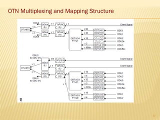
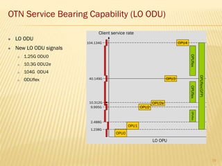
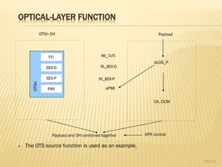
![OTN MULTIPLEXING AND MAPPING STRUCTURE
Page16
Mapping
Multiplexing
ODTUG3
ODTUG2
OChr
OChr
OChr
OCh
OCh
OCh
OTU3[V]
OTU2[V]
OTU1[V]
Client signal
Client signal
OPU3ODU3
OCCr
OCCr
OCCr
OCC
OCC
OCC
OCG-nr.m
1 ≤ i+j+k ≤ n
OCG-n.m
1 ≤ i+j+k ≤ n
OPU2ODU2
1
OPU1ODU1
OTM-nr.m
OTS, OMS, OCh, COMMSOSC OOS
OTM-n.m
4
1
14
161
11
1
1
1
1
1
1
1
1
1
1
1
1
1
1
i
j
k
i
j
1
Clientsignal
1
OTM-0.m
k](https://image.slidesharecdn.com/jc1qlvxvttiome720aj3-140610151857-phpapp01/85/OTN-for-Beginners-16-320.jpg)
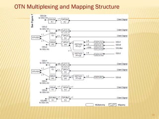

![ODUK (TDM)
Low-rate ODUk signals are multiplexed into high-
rate ODUk signals using time-division multiplexing:
A maximum of four ODU1 signals are multiplexed into
one ODU2 signal using time-division multiplexing.
Hybrid j (j 4) ODU2 and 16-4j ODU1 signals are
multiplexed into one ODU3 signal using time-division
multiplexing.
Multiple LO ODUi[j] signals at different levels are
multiplexed into one HO ODUk signal.
Page24](https://image.slidesharecdn.com/jc1qlvxvttiome720aj3-140610151857-phpapp01/85/OTN-for-Beginners-24-320.jpg)
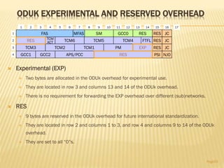
![OPUK PAYLOAD STRUCTURE IDENTIFIER
Payload structure identifier (PSI)
One byte is allocated in the OPUk overhead
to transport a 256-byte payload structure
identifier (PSI) signal.
It is aligned with the ODUk multiframe.
PSI[0] contains a one-byte payload type.
PSI[1] to PSI[255] are mapping and
concatenation specific.
Page54
255
0
1
PT
Mapping
and concatenation
specific
RES
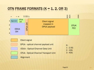
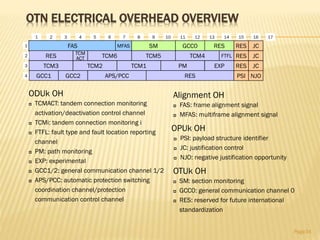
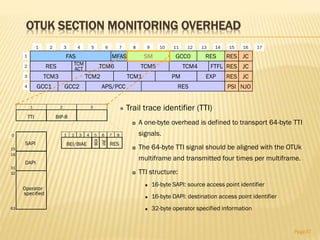
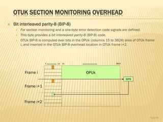
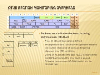
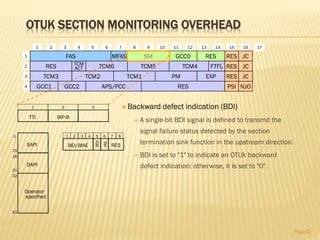
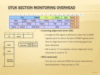
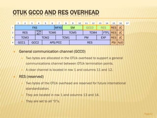
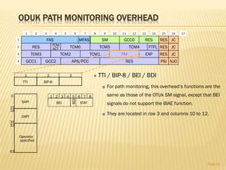
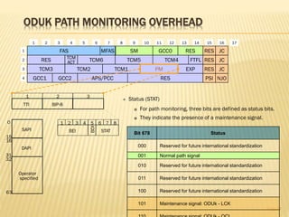
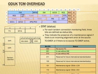
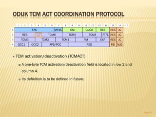
1 2 3 4 5 6 7 8 9 10 11 12 13 14 15 16
1
2
3
4
TCM3
TCM6 TCM5
TCM2
TCM4TCM
ACT
GCC1
RES JC
RES JC
NJOAPS/PCC RES
EXP
FAS RES JCRES
17
MFAS SM GCC0
PMTCM1
GCC2
FTFL
PSI](https://image.slidesharecdn.com/jc1qlvxvttiome720aj3-140610151857-phpapp01/85/OTN-for-Beginners-54-320.jpg)


An Optical Transport Network (OTN) uses optical fiber links to connect network elements and provide transport, multiplexing, routing, management and protection of client signals. OTN applies these functions from SDH/SONET to DWDM networks, and offers stronger error correction, more monitoring levels and transparent transport of client signals compared to SDH/SONET. This document describes OTN architecture, interfaces and standards, the optical transport hierarchy of multiplexing ODUk, OPUk and OTUk signals, and the containment and frame rates of these signals.