Downloaded 149 times
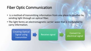
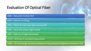
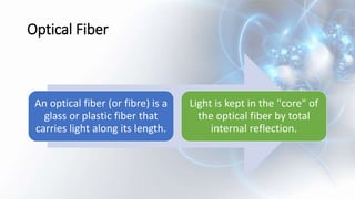

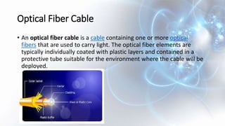

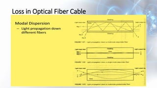
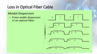

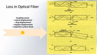
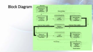


The document provides an overview of fiber optics communication, detailing its history, components, advantages, and disadvantages. It explains the differences between single-mode and multi-mode fibers, their applications, and essential concepts such as attenuation, dispersion, and the physics governing light transmission. The text also describes the role of transmitters and receivers in fiber optic systems and outlines issues like coupling losses and construction methods.


