Downloaded 1,911 times


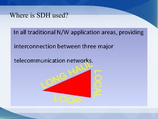


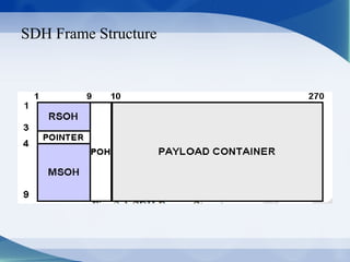

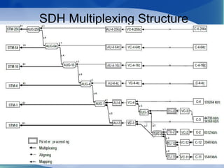
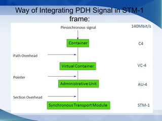

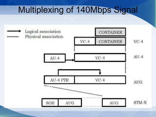
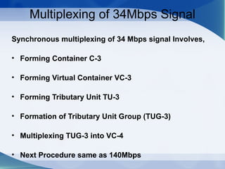
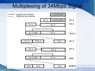
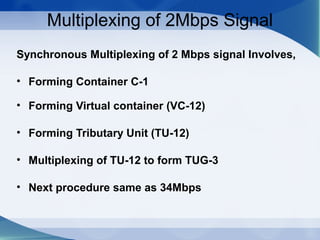
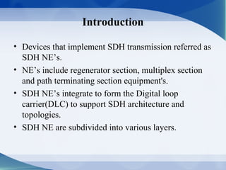
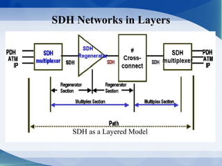
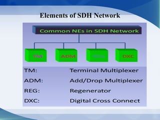
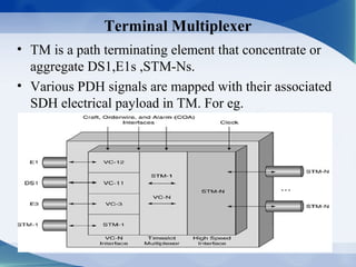


This document provides an overview of Synchronous Digital Hierarchy (SDH) including its introduction, components, frame structure, and applications. SDH was developed to provide a standardized digital transmission network with vendor independence. It uses optical fiber to enable end-to-end monitoring and self-healing ring architectures for survivability. The SDH frame structure consists of sections for transport overhead (TOH), path overhead (POH), and payloads. SDH supports multiplexing of various signals like E1, DS1, and STM streams. It allows dynamic bandwidth allocation and is a platform for future services.


