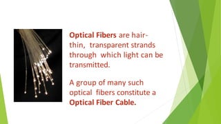
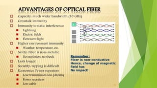
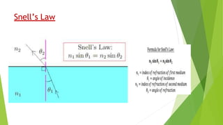
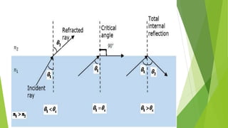
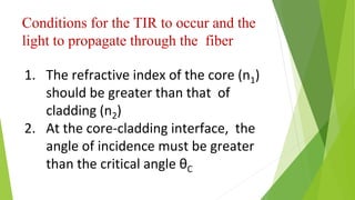
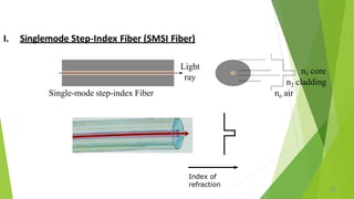
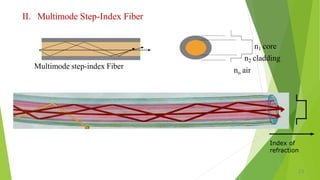
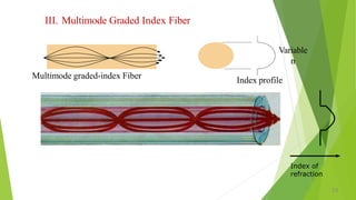
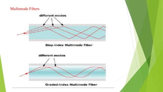
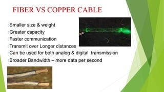
Fiber Optics
(Optical Fiber Communication)
What is an Optical Fiber?
▶ An optical fiber is a wave guide through which EM waves of optical
frequencies can be made to travel through it for long distances.
▶ But, what is a wave guide?
▶ A waveguide is a structure that guides waves, such as electromagnetic
waves or sound,or light with minimal loss of energy by restricting the
transmission of energy to one direction.
▶ (Ex: A coaxial copper cable)
Optical Fibers are hair-
thin, transparent strands
through which light can be
transmitted.
A group of many such
optical fibers constitute a
Optical Fiber Cable.
Advantages of Optical Fibers:
▶ 1.High Speed of communication(signals are transmitted at speed of light).
▶ 2.Minimum attenuation of signals(minimum losses).
▶ 3.Large Bandwidth of signals(More signals can be transmitted).
▶ 4.Low cost per cable length.
▶ 5.Can sustain adverse atmospheric conditions.
Snell’s Law
Principle of operation:
▶ It works on the principle of TIR(Total Internal Reflection).
▶ Total internal reflection(TIR) is an optical phenomenon that happens when a ray
of light strikes a medium boundary at an angle larger than a particular critical
angle with respect to the normal to the surface. (in simple terms: “when the
angle of incidence is greater that the critical angle, then the light ray is totally
reflected back into the original medium-this is TIR”)
Optical Fiber Construction:
An optical fiber consists of a central cylinder called CORE.
The CORE is surrounded by another cylinder called CLADDING.
Both CORE & CLADDING are encapsulated in a protective COATING called BUFFER JACKET.
The Refractive Index of CORE is always greater than CLADDING.
Conditions for the TIR to occur and the
light to propagate through the fiber
1. The refractive index of the core (n1)
should be greater than that of
cladding (n2)
2. At the core-cladding interface, the
angle of incidence must be greater
than the critical angle θC
Optical Fiber Classification:
▶ Optical Fibers are classified into 3 categories:
Optical Fibers
Based on type of
material
Based on Mode of
propagation
Based on Refractive
Index
Optical Fibers
Based on type of
material
Based on Mode of
propagation
Based on Refractive
Index
1.All Glass Fibers
• 2.All Plastic Fibers
3.Glass Core Plastic clad Fibers
• 4.PCS(Polymer clad silica ) Fibers
1.Single Mode Fiber
2.Multi Mode Fiber
1.Step-Index Fiber
2.Graded Index Fiber
Single Mode Fibers
▶ Single Mode cable is a glass fiber with a relatively narrow diameter of 8.3 to 10 microns that
has only one mode of transmission (Only one path for the light propagation), used to transmit one
signal per fiber (in telephone and cable TV)
▶ Single Mode Fiber gives higher transmission rate and up to 50 times more distance than multimode.
▶ It Carries higher bandwidth than multimode fiber, but requires a light source with a narrow width.
▶ Single-mode fiber has a much smaller core than multimode.
SINGLE MODE FIBER
Advantages:
 Minimum dispersion: all rays take same path, same time
to travel down the cable. A pulse can be reproduced at the
receiver very accurately.
 Less attenuation, can run over longer distance without
repeaters.
 Larger bandwidth and higher information rate
Disadvantages:
 Difficult to couple light in and out of the tiny core
 Highly directive light source (laser) is required
 Interfacing modules are more expensive
Multi-Mode Fiber
▶ Multi-Mode Fiber has more than one path (mode) for the propagation of light with a
larger diameter in the range 50-100 micron for the light to propagate.
▶ Multimode fiber gives a high bandwidth at high speeds over medium distances.
▶ Light waves are dispersed into numerous paths, or modes and hence leads to signal
distortion resulting in incomplete data transmission.
▶ Typical multimode fiber core diameters are 50, 62.5, and 100 micrometers.
Step-index & Graded Index fibers
A step-index fiber is one which has a uniform refractive index within the core and a sharp
decrease ( a s t e p c h a n g e ) in refractive index at the core-cladding interface so that
the cladding is of a lower refractive index.
A gradient-index fiber is an optical fiber whose core has a refractive index that
decreases with increasing radial distance from the optical axis of the fiber in a parabolic manner.
Multi mode graded index fiber
I. Singlemode Step-Index Fiber (SMSI Fiber)
Single-mode step-index Fiber
n1 core
n2 cladding
no air
Light
ray
Index of
refraction
22
II. Multimode Step-Index Fiber
Multimode step-index Fiber
n1 core
n2 cladding
no air
Index of
refraction
23
III. Multimode Graded Index Fiber
Variable
n
Index profile
Multimode graded-index Fiber
Index of
refraction
24
Multimode Fibers
MULTIMODE FIBER
 Multimode step-index Fibers:
🞑 inexpensive
🞑 easy to couple light into Fiber
🞑 result in higher signal distortion
🞑 lower TX rate
 Multimode graded-index Fiber:
🞑 intermediate between the other two types of Fibers
ACCEPTANCE ANGLE
 Acceptance angle is maximum angle at which a light
ray enters into core and propagate through it in zigzag
path
Acceptance
angle
ACCEPTANCE CONE
 If all possible direction of acceptance angle are
considered at same time we get a cone corresponding to
surface known as acceptance cone
NUMERICAL APERTURE
 It defines gathering capability of fiber mathematically expressed
as sine of acceptance angle
 High Numerical Aperture increases dispersion hence low
Numerical Aperture is desirable
V- NUMBER
 No. of modes supported by optical fiber is obtained
by cut-off condition known as normalized frequency
or V-Number
 Number of modes (N) = ½ V²
 V- number can be reduced either by reducing numerical
aperture or by reducing diameter of fiber
Numerical Aperture & Acceptance angle
▶ The Numerical Aperture (NA) is a maximum light gathering capacity of an optical fiber.
▶
▶ Where, n1 is the refractive index of core ,
▶ n2 is the refractive index of cladding.
▶ Acceptance angle (θ): It is the maximum angle made by the light ray with the fiber axis, so that
light can propagate through the fiber after total internal reflection.
▶ θ = sin-1(NA)
Attenuation
▶ Attenuation is the loss of optical power as light travels along the fiber.
▶ Attenuation in an optical fiber is caused by absorption, scattering, and bending
losses.
Signal attenuation is defined as the ratio of optical input power (Pi) to the optical output
power (Po).
Optical input power is the power injected into the fiber from an optical
source. Optical output power is the power received at the fiber end or
optical detector. The following equation defines signal attenuation as a
unit of length:
Length (L) is expressed in kilometers.
Therefore, the unit of attenuation is decibels/kilometer (dB/km).
Attenuation
Absorption Scattering Bending
ABSORPTION
▶ Absorption is defined as the portion of attenuation resulting from the
conversion of optical power into another energy form, such as heat.
▶ Absorption in optical fibers is explained by three factors:
▶ Imperfections in the atomic structure of the fiber material
▶ The intrinsic or basic fiber-material properties
▶ The extrinsic (presence of impurities) fiber-material properties
Scattering & Bending losses
▶ SCATTERING. - Basically, scattering losses are caused by the interaction of light with
density fluctuations within a fiber.
▶ During manufacturing, regions of higher and lower molecular density areas, relative
to the average density of the fiber, are created. Light traveling through the fiber
interacts with the density areas, Light is then partially scattered in all directions.
▶ BENDING LOSSES. - Bending the fiber also causes attenuation. Bending loss is
classified according to the bend radius of curvature.
MICRO BENDING LOSSES
•Micro-bend Losses are caused by small
discontinuities or imperfections in the fiber.
•Micro bending is a loss due to small bending or
distortions. This small micro bending is not
visible.
•The losses due to this are temperature related,
tensile related or crush related.
•Uneven coating applications and improper
cabling procedure increases micro bend loss.
External forces are also a source of micro
bends.
T
ransmitter
▶
▶
Encoder Driver
Circuit
Light
Source
Photo
Detector
Amplifier
Signal
Restorer Decoder
Receiver
Transmitter
Analog signal
Analog signal
i/p
o/p
OF
OF
Optical Fiber Communication System
Working:
▶ Encoder: It is an electronic system that conerts analog information (voice/data/objects
etc.) into binary data. The binary data may be a series of electrical pulses.
▶ Transmitter
▶ It consists of two parts:
▶ 1.Driver ckt:It supplies electrical signals to the light source from the encoder in the
required sequential form.
▶ 2.Light source:It is an LED or a LASER diode which converts electrical signals to optical
signals.
▶ O/P from the light source is sent to an Optical Fiber.
▶ Receiver: It consists of 3 parts:
▶ 1.Photo detector:It converts optical signals into equivalent electrical signals and
supplies them to amplifier.
▶ 2.Amplifier:It amplifies the signals and sends them to signal restorer.
▶ 3.Signal Restorer:It keeps all signals in sequential form and supplies them to decoder
in a suitable way.
▶ Decoder: It converts the received signals into analog information form.
 In Telecommunications totransfer data
 In Local Area Networks to share internet connections.
 In Cable TV and CCTV.
 In Optical Fiber Sensors.
 In Endoscopy to view internal body organs.
 In decoration
APPLICATIONS
 Used in Cable T
.V. , HDTV, LANs & CCTV systems
 Used in Optic Fiber Communication for transmission of analog &
digital data
 Used in Imaging Optics & Spectroscopy
 Used in illumination applications
 Used in various military applications
 Fiber optic sensors & couplers
FIBER VS COPPER CABLE
🞑Smaller size & weight
🞑Greater capacity
🞑Faster communication
🞑Transmit over Longer distances
🞑Can be used for both analog & digital transmission
🞑Broader Bandwidth – more data per second
FIBER VS COPPER CABLE (CONTD.)
🞑Immunity to Electromagnetic Interference
🞑Low attenuation/transmission loss over long distances
🞑Electrical Insulator
🞑Lack of costly metal conductor
🞑Dielectric waveguide
🞑Signal Security
FIBER VS CO-AXIAL
CABLE
 More information carrying capacity with higher data rates and fidelity
 Greater transmission speed
 Smaller in size and light in weight
 Easier to handle and install
 Immune towards environmental hazards & electromagnetic
interference
 Higher Bandwidth
 Economical
 Low signal loss
DISADVANTAGES
 Cumulative losses due to large size of fiber couplers
 Hazardous emissions like glass shards & optical
radiation
 Requires technicians with special expertise for installation &
maintenance
optical fibers.pptx

optical fibers.pptx

  • 1.
  • 2.
    What is anOptical Fiber? ▶ An optical fiber is a wave guide through which EM waves of optical frequencies can be made to travel through it for long distances. ▶ But, what is a wave guide? ▶ A waveguide is a structure that guides waves, such as electromagnetic waves or sound,or light with minimal loss of energy by restricting the transmission of energy to one direction. ▶ (Ex: A coaxial copper cable)
  • 4.
    Optical Fibers arehair- thin, transparent strands through which light can be transmitted. A group of many such optical fibers constitute a Optical Fiber Cable.
  • 6.
    Advantages of OpticalFibers: ▶ 1.High Speed of communication(signals are transmitted at speed of light). ▶ 2.Minimum attenuation of signals(minimum losses). ▶ 3.Large Bandwidth of signals(More signals can be transmitted). ▶ 4.Low cost per cable length. ▶ 5.Can sustain adverse atmospheric conditions.
  • 7.
  • 8.
    Principle of operation: ▶It works on the principle of TIR(Total Internal Reflection). ▶ Total internal reflection(TIR) is an optical phenomenon that happens when a ray of light strikes a medium boundary at an angle larger than a particular critical angle with respect to the normal to the surface. (in simple terms: “when the angle of incidence is greater that the critical angle, then the light ray is totally reflected back into the original medium-this is TIR”)
  • 11.
    Optical Fiber Construction: Anoptical fiber consists of a central cylinder called CORE. The CORE is surrounded by another cylinder called CLADDING. Both CORE & CLADDING are encapsulated in a protective COATING called BUFFER JACKET. The Refractive Index of CORE is always greater than CLADDING.
  • 12.
    Conditions for theTIR to occur and the light to propagate through the fiber 1. The refractive index of the core (n1) should be greater than that of cladding (n2) 2. At the core-cladding interface, the angle of incidence must be greater than the critical angle θC
  • 14.
    Optical Fiber Classification: ▶Optical Fibers are classified into 3 categories: Optical Fibers Based on type of material Based on Mode of propagation Based on Refractive Index
  • 15.
    Optical Fibers Based ontype of material Based on Mode of propagation Based on Refractive Index 1.All Glass Fibers • 2.All Plastic Fibers 3.Glass Core Plastic clad Fibers • 4.PCS(Polymer clad silica ) Fibers 1.Single Mode Fiber 2.Multi Mode Fiber 1.Step-Index Fiber 2.Graded Index Fiber
  • 16.
    Single Mode Fibers ▶Single Mode cable is a glass fiber with a relatively narrow diameter of 8.3 to 10 microns that has only one mode of transmission (Only one path for the light propagation), used to transmit one signal per fiber (in telephone and cable TV) ▶ Single Mode Fiber gives higher transmission rate and up to 50 times more distance than multimode. ▶ It Carries higher bandwidth than multimode fiber, but requires a light source with a narrow width. ▶ Single-mode fiber has a much smaller core than multimode.
  • 17.
    SINGLE MODE FIBER Advantages: Minimum dispersion: all rays take same path, same time to travel down the cable. A pulse can be reproduced at the receiver very accurately.  Less attenuation, can run over longer distance without repeaters.  Larger bandwidth and higher information rate Disadvantages:  Difficult to couple light in and out of the tiny core  Highly directive light source (laser) is required  Interfacing modules are more expensive
  • 18.
    Multi-Mode Fiber ▶ Multi-ModeFiber has more than one path (mode) for the propagation of light with a larger diameter in the range 50-100 micron for the light to propagate. ▶ Multimode fiber gives a high bandwidth at high speeds over medium distances. ▶ Light waves are dispersed into numerous paths, or modes and hence leads to signal distortion resulting in incomplete data transmission. ▶ Typical multimode fiber core diameters are 50, 62.5, and 100 micrometers.
  • 20.
    Step-index & GradedIndex fibers A step-index fiber is one which has a uniform refractive index within the core and a sharp decrease ( a s t e p c h a n g e ) in refractive index at the core-cladding interface so that the cladding is of a lower refractive index. A gradient-index fiber is an optical fiber whose core has a refractive index that decreases with increasing radial distance from the optical axis of the fiber in a parabolic manner. Multi mode graded index fiber
  • 22.
    I. Singlemode Step-IndexFiber (SMSI Fiber) Single-mode step-index Fiber n1 core n2 cladding no air Light ray Index of refraction 22
  • 23.
    II. Multimode Step-IndexFiber Multimode step-index Fiber n1 core n2 cladding no air Index of refraction 23
  • 24.
    III. Multimode GradedIndex Fiber Variable n Index profile Multimode graded-index Fiber Index of refraction 24
  • 25.
  • 26.
    MULTIMODE FIBER  Multimodestep-index Fibers: 🞑 inexpensive 🞑 easy to couple light into Fiber 🞑 result in higher signal distortion 🞑 lower TX rate  Multimode graded-index Fiber: 🞑 intermediate between the other two types of Fibers
  • 28.
    ACCEPTANCE ANGLE  Acceptanceangle is maximum angle at which a light ray enters into core and propagate through it in zigzag path Acceptance angle
  • 30.
    ACCEPTANCE CONE  Ifall possible direction of acceptance angle are considered at same time we get a cone corresponding to surface known as acceptance cone
  • 31.
    NUMERICAL APERTURE  Itdefines gathering capability of fiber mathematically expressed as sine of acceptance angle  High Numerical Aperture increases dispersion hence low Numerical Aperture is desirable
  • 33.
    V- NUMBER  No.of modes supported by optical fiber is obtained by cut-off condition known as normalized frequency or V-Number  Number of modes (N) = ½ V²  V- number can be reduced either by reducing numerical aperture or by reducing diameter of fiber
  • 35.
    Numerical Aperture &Acceptance angle ▶ The Numerical Aperture (NA) is a maximum light gathering capacity of an optical fiber. ▶ ▶ Where, n1 is the refractive index of core , ▶ n2 is the refractive index of cladding. ▶ Acceptance angle (θ): It is the maximum angle made by the light ray with the fiber axis, so that light can propagate through the fiber after total internal reflection. ▶ θ = sin-1(NA)
  • 36.
    Attenuation ▶ Attenuation isthe loss of optical power as light travels along the fiber. ▶ Attenuation in an optical fiber is caused by absorption, scattering, and bending losses. Signal attenuation is defined as the ratio of optical input power (Pi) to the optical output power (Po). Optical input power is the power injected into the fiber from an optical source. Optical output power is the power received at the fiber end or optical detector. The following equation defines signal attenuation as a unit of length: Length (L) is expressed in kilometers. Therefore, the unit of attenuation is decibels/kilometer (dB/km).
  • 37.
  • 38.
    ABSORPTION ▶ Absorption isdefined as the portion of attenuation resulting from the conversion of optical power into another energy form, such as heat. ▶ Absorption in optical fibers is explained by three factors: ▶ Imperfections in the atomic structure of the fiber material ▶ The intrinsic or basic fiber-material properties ▶ The extrinsic (presence of impurities) fiber-material properties
  • 39.
    Scattering & Bendinglosses ▶ SCATTERING. - Basically, scattering losses are caused by the interaction of light with density fluctuations within a fiber. ▶ During manufacturing, regions of higher and lower molecular density areas, relative to the average density of the fiber, are created. Light traveling through the fiber interacts with the density areas, Light is then partially scattered in all directions. ▶ BENDING LOSSES. - Bending the fiber also causes attenuation. Bending loss is classified according to the bend radius of curvature.
  • 41.
  • 42.
    •Micro-bend Losses arecaused by small discontinuities or imperfections in the fiber. •Micro bending is a loss due to small bending or distortions. This small micro bending is not visible. •The losses due to this are temperature related, tensile related or crush related. •Uneven coating applications and improper cabling procedure increases micro bend loss. External forces are also a source of micro bends.
  • 43.
  • 44.
    Working: ▶ Encoder: Itis an electronic system that conerts analog information (voice/data/objects etc.) into binary data. The binary data may be a series of electrical pulses. ▶ Transmitter ▶ It consists of two parts: ▶ 1.Driver ckt:It supplies electrical signals to the light source from the encoder in the required sequential form. ▶ 2.Light source:It is an LED or a LASER diode which converts electrical signals to optical signals. ▶ O/P from the light source is sent to an Optical Fiber.
  • 45.
    ▶ Receiver: Itconsists of 3 parts: ▶ 1.Photo detector:It converts optical signals into equivalent electrical signals and supplies them to amplifier. ▶ 2.Amplifier:It amplifies the signals and sends them to signal restorer. ▶ 3.Signal Restorer:It keeps all signals in sequential form and supplies them to decoder in a suitable way. ▶ Decoder: It converts the received signals into analog information form.
  • 47.
     In Telecommunicationstotransfer data  In Local Area Networks to share internet connections.  In Cable TV and CCTV.  In Optical Fiber Sensors.  In Endoscopy to view internal body organs.  In decoration
  • 48.
    APPLICATIONS  Used inCable T .V. , HDTV, LANs & CCTV systems  Used in Optic Fiber Communication for transmission of analog & digital data  Used in Imaging Optics & Spectroscopy  Used in illumination applications  Used in various military applications  Fiber optic sensors & couplers
  • 49.
    FIBER VS COPPERCABLE 🞑Smaller size & weight 🞑Greater capacity 🞑Faster communication 🞑Transmit over Longer distances 🞑Can be used for both analog & digital transmission 🞑Broader Bandwidth – more data per second
  • 50.
    FIBER VS COPPERCABLE (CONTD.) 🞑Immunity to Electromagnetic Interference 🞑Low attenuation/transmission loss over long distances 🞑Electrical Insulator 🞑Lack of costly metal conductor 🞑Dielectric waveguide 🞑Signal Security
  • 51.
    FIBER VS CO-AXIAL CABLE More information carrying capacity with higher data rates and fidelity  Greater transmission speed  Smaller in size and light in weight  Easier to handle and install  Immune towards environmental hazards & electromagnetic interference  Higher Bandwidth  Economical  Low signal loss
  • 52.
    DISADVANTAGES  Cumulative lossesdue to large size of fiber couplers  Hazardous emissions like glass shards & optical radiation  Requires technicians with special expertise for installation & maintenance