www.huawei.com
Copyright © 2006 Huawei Technologies Co., Ltd. All rights reserved.
WDM Principle
Copyright © 2006 Huawei Technologies Co., Ltd. All rights reserved. Page2
Foreword
 With the development of telecommunication, the
requirements of the transmission capacity and service
categories are becoming bigger and bigger, under this
background, WDM technology emerged.
Copyright © 2006 Huawei Technologies Co., Ltd. All rights reserved. Page3
Objectives
 Upon completion of this course, you will be able to:

Describe the concepts, transmission modes and structure
of WDM;

Classify the different types and characteristics of the fiber;

Outline the key technologies of WDM system;

List the technical specifications for WDM system.
Copyright © 2006 Huawei Technologies Co., Ltd. All rights reserved. Page4
Contents
1. WDM Overview
2. Transmission Media
3. Key Technologies
4. Master Limitation of DWDM system
5. Technical Specifications
Copyright © 2006 Huawei Technologies Co., Ltd. All rights reserved. Page5
Solution of capacity expansion
 SDM
 Add fiber &
equipment
 Time & cost
 TDM
 STM-16 STM-64
→
 Cost &
Complication
 WDM
 Economical &
Mature & Quick
How to increase network capacity ?
Copyright © 2006 Huawei Technologies Co., Ltd. All rights reserved. Page6
What's WDM ?
Free Way
Gas Station
Patrol Car
Copyright © 2006 Huawei Technologies Co., Ltd. All rights reserved. Page7
WDM Concept
1
2
┋
1 2 n
┉

n
SDH signal
IP package
ATM cells
 Different signals with specific wavelength are
multiplexed into a fiber for transmission.
Copyright © 2006 Huawei Technologies Co., Ltd. All rights reserved. Page8
 The overall structure of the WDM system of N-path
wavelength:

Optical Transponder Unit (OTU)

Optical Multiplexer Unit / Optical De-multiplexer Unit
(OMU/ODU)

Optical Amplifier (OA)

Supervisory Channel (OSC/ESC)
System Structure
OTU
OTU
OTU
O
M
U
O
D
U
OTU
OTU
OTU
OSC OSC
OSC
LA
BA PA
Copyright © 2006 Huawei Technologies Co., Ltd. All rights reserved. Page9
Transmission Modes
 Single fiber unidirectional transmission
M
4
0
M
4
0
MUX DMUX
O
T
U
O
T
U
Copyright © 2006 Huawei Technologies Co., Ltd. All rights reserved. Page10
M
4
0
M
4
0
MUX/DMUX DMUX/MUX
Transmission Modes
 Single fiber bidirectional transmission
O
T
U
O
T
U
Copyright © 2006 Huawei Technologies Co., Ltd. All rights reserved. Page11
Application Modes
 Open System
M
4
0
M
4
0
MUX DMUX
O
T
U
O
T
U
Client Client
Copyright © 2006 Huawei Technologies Co., Ltd. All rights reserved. Page12
Application Modes
 Integrated System
M
4
0
M
4
0
MUX DMUX
Client Client
Copyright © 2006 Huawei Technologies Co., Ltd. All rights reserved. Page13
Advantages of WDM
 Ultra high capacity
 Data transparency transmission
 Long haul transmission
 Compatible with existing optical fibers
 High performance-to-cost ratio
 High networking flexibility, economy and reliability
 Smooth expansion
Copyright © 2006 Huawei Technologies Co., Ltd. All rights reserved. Page14
CWDM vs. DWDM
 CWDM: Coarse
wavelength division
multiplexing

spacing of two adjacent
wavelengths: 20 nm
192 wavelengths at the extended C band with 25 GHz channel
spacing
196.05THz 192.125THz
160 wavelengths at C band
192.05THz
32 extended
wavelengths
191.275THz
ITU-T G.694.1
 DWDM: dense wavelength division
multiplexing

spacing of two adjacent wavelengths: 25 GHz
Copyright © 2006 Huawei Technologies Co., Ltd. All rights reserved. Page15
Distribution of Optical Wavelength
Areas
 Nominal central frequency refers to the central wavelength
corresponding to each channel in WDM systems. Channel
frequency allowed in G.692 is based on frequency and spacing
series of reference frequency 193.1THz and minimum spacing
100GHz , 50GHz or 25GHz.
Copyright © 2006 Huawei Technologies Co., Ltd. All rights reserved. Page16
Questions
 What are WDM, DWDM and CWDM?
 Difference between the two transmission modes
 Difference between the two application modes
 List the structure of the WDM system.
Copyright © 2006 Huawei Technologies Co., Ltd. All rights reserved. Page17
 Basic concepts and features of WDM, DWDM and CWDM;
 WDM system structure ;
 Transmission and application Modes of WDM system;
Summary
Copyright © 2006 Huawei Technologies Co., Ltd. All rights reserved. Page18
Contents
1. WDM Overview
2. Transmission Media
3. Key Technologies
4. Master limitation of DWDM system
5. Technical Specifications
Copyright © 2006 Huawei Technologies Co., Ltd. All rights reserved. Page19
Structure of Optical Fiber
 Consists of a cylindrical glass core, a glass cladding and a
plastic wear-resisting coating.
θ
n2
n1
Refraction
Reflection
Cladding
Core
Coating
Copyright © 2006 Huawei Technologies Co., Ltd. All rights reserved. Page20
Characteristics of Fiber
 Loss
 Dispersion
 Non-linear
Copyright © 2006 Huawei Technologies Co., Ltd. All rights reserved. Page21
Characteristics of Fiber Loss
 Fiber loss is classified into:

Absorption loss

Scattering loss

Bending loss
 The fiber loss can be calculated according to the
following formula:

Fiber loss (dB) = fiber length (km) x fiber loss coefficient
(dB/km)
Copyright © 2006 Huawei Technologies Co., Ltd. All rights reserved. Page22
Attenuation
900 1300 1400 1500 1600 1700
nm
dB/km
2
3
1
4
5
1200
Multi-mode
(
850~900nm
) O
band
E S C L U
OH-
 Attenuation varies with wavelengths.
 The attenuation around 1380 nm goes up sharply due to absorption by hydroxyl ions. This is generally
called "water peak".
 As we can see, the attenuation in C band and F band is the lowest.
Copyright © 2006 Huawei Technologies Co., Ltd. All rights reserved. Page23
Wavelength Ranges in WDM
Band Description Range (nm) Bandwidth (nm)
O band Original 1260–1360 100
E band Extension 1360–1460 100
S band Short 1460–1525 65
C band Normal 1525–1565 40
L band Long 1565–1625 60
U band Ultra-long 1625–1675 50
In a DWDM system, C band and L band are used because the attenuation in the two bands is the
lowest.
In a CWDM system, multiple bands are used, ranging from 1311 to 1611 nm, because attenuation
is not a major restrictive factor in short-distance transmission.
Copyright © 2006 Huawei Technologies Co., Ltd. All rights reserved. Page24
 Fiber dispersion can be classified into:

Mode dispersion

Chromatic dispersion

Polarization mode dispersion
 Dispersion: a physical phenomenon of signal distortion
caused when various modes carrying signal energy or
different frequencies of the signal have different group
velocity and disperse from each other during propagation.
Characteristics of Fiber Dispersion
Copyright © 2006 Huawei Technologies Co., Ltd. All rights reserved. Page25
Chromatic Dispersion
 Chromatic dispersion:

pulse broadening, cause intersymbol interference
 The chromatic dispersion can be calculated according to
the following formula:

CD (ps/nm) = fiber length (km) x CD coefficient (ps/km.nm)
Time
Power
Optical pulses
Transmitting
L1 (km)
Transmitting
L2 (km)
Copyright © 2006 Huawei Technologies Co., Ltd. All rights reserved. Page26
PMD
 PMD occurs when optical signals in two orthogonal polarizations travel at
different speeds in optical fibers. PMD is one of critical parameters related to
optical fibers.
 PMD occurs randomly. So it is a random variable.
 PMD has the same impact as CD has: resulting in pulse broadening.
Copyright © 2006 Huawei Technologies Co., Ltd. All rights reserved. Page27
According to ITU-T, three types of single-mode optical fibers are defined in G.652, G.653, and G.655
respectively. The differences between them are shown in the following table:
Type Definition Scope Main Specifications
G.652
The standard single-mode fiber
(SMF) refers to the fiber whose
zero-dispersion point (the zero-
dispersion wavelength) is near
to 1310 nm.
Used in both SDH
system and DWDM
system
Attenuation: The attenuation value of the 1310 nm band is
0.3–0.4 dB/km and the typical value is 0.35 dB/km. The
attenuation value of the 1550 nm band is 0.17–0.25 dB/km
and the typical value is 0.20 dB/km.
Dispersion: The allowed value of the zero-dispersion
wavelength is 1300–1324 nm. The dispersion coefficient of
the 1550 nm band is positive and the typical value of the
dispersion coefficient D is 17 ps/(nm.km). The maximum
value is not more than 20 ps/(nm.km).
G.653
Dispersion-shifted fiber (DSF)
refers to the fiber whose zero-
dispersion point is near to 1550
nm. Compared with G.652 SMF,
the zero-dispersion point of
G.653 DSF shifts.
Used in the SDH
system but not in
the DWDM system
Attenuation: The attenuation value of the 1310 nm band is
less than 0.55 dB/km and the typical value has not been
confirmed. The attenuation value of the 1550 nm band is
less than 0.35 dB/km and the typical value is 0.19–0.25
dB/km.
Dispersion: The wavelengths in the G.653 DSF are near to
1550 nm, usually 1525–1575 nm. The maximum dispersion
coefficient is 3.5 ps/(nm.km). The dispersion coefficient in
the DSF is too small or may be 0 for 1550 nm bands,
especially C band.
G.655
Non-zero dispersion-shifted
fiber (NZDSF) refers to the fiber
whose zero-dispersion point is
shifted away from 1550 nm
and not within the DWDM
operating wavelength range
Used in both SDH
system and DWDM
system, but more
applicable to the
DWDM system
Attenuation: The attenuation value of the 1310 nm band is
not specified in ITU-T. The attenuation value of the 1550
nm band is less than 0.35 dB/km, usually 0.19–0.25 dB/km.
Dispersion: If 1530 nm <  < 1565 nm, 0.1 ps/(nm.km) < |
D(λ)| < 6.0 ps/(nm.km). The typical value of the dispersion
coefficient of the G.655 NZDSF varies with vendors and
G.652/G.653/G.655 Single-Mode Optical
Fibers
Copyright © 2006 Huawei Technologies Co., Ltd. All rights reserved. Page28
Dispersion
coefficient
G.655
1550nm
1310nm
17ps/nm.km
¦ Ë
Dispersion
G.652:widely used, need
dispersion compensation
for high rate transmission
G.653: Zero dispersion
at 1550nm window.
G.655: Little dispersion
to avoid FWM.
Copyright © 2006 Huawei Technologies Co., Ltd. All rights reserved. Page29
Non-Linear Effects of Single-Mode Optical
Fibers
 Fiber Non-linear effects can be classified into:

Stimulated non-flexible scattering: stimulated Raman scattering
(SRS) and stimulated Brillouin scattering (SBS)

Kerr-effect: self-phase modulation (SPM), cross-phase modulation
(XPM) and four wave mixing (FWM)
Copyright © 2006 Huawei Technologies Co., Ltd. All rights reserved. Page30
SRS
Short wavelength, pump,
and long wavelength
Impacts on the system:
Power unbalance in the
channel
Inter-channel Raman
crosstalk
l
P
l
P
Input Output
Copyright © 2006 Huawei Technologies Co., Ltd. All rights reserved. Page31
SBS
• A non-linear phenomenon causing the strong
forward transmission signal converted to backward
transmission when the signal optical power exceeds
the SBS threshold
• SBS power threshold: 9 dBm for single wavelength
channel
Impacts on the system:
When the value exceeds the threshold, strong
backward scattering is caused and intensity noise is
repeated.
Copyright © 2006 Huawei Technologies Co., Ltd. All rights reserved. Page32
XPM/SPM
Self-Phase Modulation (SPM)
The phase varies with the strength of light and is transformed into
waveform distortion.
The impact varies directly with incident power in the channel and is
accumulated along the fiber and transmission sections.
Cross-Phase Modulation (XPM)
Phase modulation is affected by other channels and the change of phase
due to fiber dispersion causes intensity noises.
Increase the channel spacing to suppress XPM.
Copyright © 2006 Huawei Technologies Co., Ltd. All rights reserved. Page33
FWM
Definition: Two or three lightwaves with different wavelength interact
with each other, which causes new lightwaves at other wavelengths or
causes new optical wavelength effect on the sideband.
Fiber
f1
f
f3 f2
f1
f
f3 f2
fFWM
Impacts: When the new frequency generated by FWM is within the
channel bandwidths, the channel strength may fluctuate and inter-
channel crosstalk may occur.
Factors: dispersion, channel number, channel spacing and signal power
Copyright © 2006 Huawei Technologies Co., Ltd. All rights reserved. Page34
Note!
 Non-linear effects cannot be eliminated or compensated
for. So they should be restricted as much as possible!
Copyright © 2006 Huawei Technologies Co., Ltd. All rights reserved. Page35
Questions
 What’s difference between the refractive index of the
cladding and core?
 What are the features of G.652, G.653 and G.655 fibers?
 What problems may occur when optical signals are
transmitted in single-mode fibers?
Copyright © 2006 Huawei Technologies Co., Ltd. All rights reserved. Page36
 Structure of optical fiber
 Types of optical fiber
 Characteristics of optical fiber
Summary
Copyright © 2006 Huawei Technologies Co., Ltd. All rights reserved. Page37
Contents
1. WDM Overview
2. Transmission Media
3. Key Technologies
4. Master limitation of WDM system
5. Technical Specifications
Copyright © 2006 Huawei Technologies Co., Ltd. All rights reserved. Page38
WDM System Key Technologies
 Optical
Source/receiver
 Optical Amplifier
 Supervisory
Technologies/cod
e technology
Key Tech. in WDM
 Optical
Multiplexer and
Demultiplexer
Copyright © 2006 Huawei Technologies Co., Ltd. All rights reserved. Page39
Requirements of Optical Source
1 Larger dispersion tolerance value
2 Standard and stable wavelength
Copyright © 2006 Huawei Technologies Co., Ltd. All rights reserved. Page40
Direct modulator
LD
Modulation current
Copyright © 2006 Huawei Technologies Co., Ltd. All rights reserved. Page41
Electro-Absorption (EA) external
modulator
LD EA
DC
current drive ITU ¦ Ë
Modulation current
Copyright © 2006 Huawei Technologies Co., Ltd. All rights reserved. Page42
DC current
drive
ITU ¦ Ë
Modulation current
LD
Mach-Zehnder (M-Z) external
modulator
Copyright © 2006 Huawei Technologies Co., Ltd. All rights reserved. Page43
Comparison of Modulators
Types Direct Modulator EA Modulator M-Z Modulator
Max. dispersion
toleration (ps/nm)
1200~4000 7200~12800
>12800
Cost moderate expensive very expensive
Wavelength Stability good better best
Copyright © 2006 Huawei Technologies Co., Ltd. All rights reserved. Page44
Wavelength Tunable Technology
 Wavelength Tunable Principle

The wavelengths corresponding to the refractive index and maximum gain
of semiconductor materials vary with the temperature, pressure, carrier
potency, and field strength. Changing these factors can realize tunable
wavelengths.

Change the temperature and carrier potency and then combine with such
technologies as MEMS, microelectronics, and lightwave circuits to produce
various tunable technologies.
 Advantages of Wavelength Tunable Technology

Reduction of spare parts stock

Flexible networking
Copyright © 2006 Huawei Technologies Co., Ltd. All rights reserved. Page45
Classification of Wavelength Tunable
Sources
 Based on the number of tunable wavelengths:

4-wavelength, 8-wavelength, 20-wavelength, 40-wavelength, 80-
wavelength, 160-wavelength…
 Based on the frequency spacing:

100 GHz, 50 GHz, and 25 GHz
 Based on the appearance and structure

Laser type: the appearance is similar to a common laser.

Module type: tunable laser + locker + control circuit
 Based on the manufacturers

Fujitsu, ioLon, Agility, Intel, BandWidth9, Princeton Optronics, Bookham,
GTRAN, QDI, Santur, Vitesse…
Copyright © 2006 Huawei Technologies Co., Ltd. All rights reserved. Page46
Wavelength Tunable Technology
Thermally tune single DFB (~3nm tuning)
Tunable DBR
SGDBR (eg Agility)
GCSR (eg Altitun)
External cavity (Iolon)
Integrated DFB (NEC)
Electrically pumped MEMs-VCSEL ( BW9)
Optically pumped MEMs-VCSEL (Coretek)
MEMs-DFB array (Santur)
Copyright © 2006 Huawei Technologies Co., Ltd. All rights reserved. Page47
Code Modulation Technology
 Simple, low-cost, and mature
 NRZ for transitional code
elements, sensitive to
transmission damage, and
inapplicable to high-speed
ultra-long-haul DWDM
transmission
 Commonly applied in mid- and
short-haul DWDM transmission
systems
… …
Conventional code
modulation technology (NRZ)
New code modulation
technology
 Reduce OSNR tolerance.
 Add dispersion tolerance and
PDM tolerance.
 Suppress pulse distortion
caused by non-linear effect of
the fiber.
 Applied in long-haul DWDM
transmission systems.
 CRZ, DRZ, ODB, DQPSK……
Copyright © 2006 Huawei Technologies Co., Ltd. All rights reserved. Page48
Comparison of coding technologies with 10 Gbit/s
rate
Coding Technology Advantage Disadvantage Application
NRZ
Narrow spectral width
Simple structure of modulation
and demodulation
Low cost
Low ability to prevent non-
linear effects
High OSNR tolerance
Low dispersion tolerance
Applied to the system with
10 Gbit/s or lower rate and
to short-and-medium
distance transmission
SuperCRZ
Great ability to prevent non-
linear effects
Lower OSNR tolerance than that
of NRZ
Wide spectrum bandwidth
Does not support 25 GHz
system
Low dispersion tolerance
Does not support wavelength
adjustable
Applied to the system with
10 Gbit/s and to long-
distance transmission
SuperDRZ
Narrow spectrum bandwidth
Supports 25 GHz system
High dispersion tolerance
Great ability to prevent non-
linear effects
Supports wavelength adjustable
Cost effective
Applied to the system with
10 Gbit/s and to long-
distance transmission
ODB
High dispersion tolerance
Great ability to prevent non-
linear effects
Supports wavelength adjustable
If the optical power of signals that
are just transmitted into the optical
fiber is great, the transmission
distance decreases because of
dispersion limited. The ODB is not
applied to long-distance
transmission.
Applied to 10 Gbit/s
metropolitan area network
Copyright © 2006 Huawei Technologies Co., Ltd. All rights reserved. Page49
Comparison of coding technologies with 40 Gbit/s
rate
COMPARE ITEM NRZ ODB DRZ ( H
W)
NRZ-
DPSK
RZ-
DQPSK
DP-QPSK
OSNR ★ ★ ★★ ★★★ ★★★ ★★★★
CD tolerance ★★ ★★★ ★★ ★★ ★★★ ★★ ★★
PMD tolerance ★ ★★ ★★ ★★ ★★★ ★★ ★★
$$ ★★★★ ★★★★ ★★★ ★★ ★★ ★
50GHz × √ × × √ √
Non-linear
tolerance
★★ ★★ ★★★ ★★★ ★★ ★
Copyright © 2006 Huawei Technologies Co., Ltd. All rights reserved. Page50
Receiver
PIN lower sensitivity (usually about -20 dBm) and higher overload point
(usually about 0 dBm); applicable to short-distance transmission
APD higher sensitivity (usually about -28 dBm) and lower overload point
(usually about -9 dBm); applicable to long-distance transmission
Copyright © 2006 Huawei Technologies Co., Ltd. All rights reserved. Page51
FEC Technology
 Forward Error Correction Technology

The transmit end adds redundant error correction codes and the receive
end decodes and corrects errors to eliminate errors on the circuit.

Reduce the OSNR tolerance of the receiver. The reduced OSNR tolerance is
called code gain.

The FEC capability varies directly with the code gain.
 Classification of FEC Technology

In-band FEC: supported by ITU-T G.707, code gain: 3 dB to 4 dB

Out-of-band FEC: supported by ITU-T G.975/709, code gain: 5 dB to 6 dB

Extremely robust FEC: no standard is available currently, highest code
gain: 7 dB to 9 dB
Copyright © 2006 Huawei Technologies Co., Ltd. All rights reserved. Page52
Optical Amplifiers
EDFA
RFA Raman Fiber Amplifier
Erbium Doped Fiber Amplifier
OA
Copyright © 2006 Huawei Technologies Co., Ltd. All rights reserved. Page53
Stimulated radiation
 Er3+
energy level diagram
Erbium Doped Fiber Amplifier
E2 meta-stable state
E3 excited state
E1 ground state
1550nm
signal light
1550nm
signal light
980nm
pump light
Decay
Copyright © 2006 Huawei Technologies Co., Ltd. All rights reserved. Page54
Structure of EDFA
Coupler
EDF
ISO
Pumping laser
ISO
PD
TAP
Signal input
TAP
Signal Output
PD
ISO: Isolator
PD: Photon Detector
Copyright © 2006 Huawei Technologies Co., Ltd. All rights reserved. Page55
Features of EDFA

Consistent with the low
attenuation window

High energy conversion
efficiency

High gain with little cross-
talk

Good gain stability
…

Fixed gain range

Gain un-flatness

Optical surge problem
…
Advantages Disadvantages
Copyright © 2006 Huawei Technologies Co., Ltd. All rights reserved. Page56
Automatic Gain Control
Pin Pout
Gain
λ1~ λn
λ1~ λn
Gain no change!
EDFA
PIN
pump
PIN
DSP
splitter splitter
EDF
Input Power: Pin Output Power: Pout
Gain = Pout / Pin is invariable
coupler
Copyright © 2006 Huawei Technologies Co., Ltd. All rights reserved. Page57
Main Performance Parameters of EDFA
 Amplified spontaneous emission noise (ASE)
 Noise figure (NF) = (S/N) in / (S/N) out 3 dB
≥
 Gain (G) = 10lg (Pout/Pin) (dB)
 Gain flatness: gain balance
 Bandwidth
Copyright © 2006 Huawei Technologies Co., Ltd. All rights reserved. Page58
Raman Fiber Amplifier
 Stimulated Raman Scattering
Pump
Gain
30nm
13THz
Pump3
70~100nm
30nm
Gain
Pump2
Pump1
Copyright © 2006 Huawei Technologies Co., Ltd. All rights reserved. Page59
Features of Raman

Flexible gain wavelength

Simple structure

Nonlinear effect can be
reduced;

Low noise
…

High pump power, low
efficiency and high cost;

Components & fiber
undertake the high power;
…
Advantages Disadvantages
Copyright © 2006 Huawei Technologies Co., Ltd. All rights reserved. Page60
Application of OA
Booster amplifier Line Amplifier Pre-amplifier
M
4
0
OTU
OTU
M
4
0
M
4
0
OTU
OTU
M
4
0
M
U
X
D
M
U
X
OA OA OA
Copyright © 2006 Huawei Technologies Co., Ltd. All rights reserved. Page61
Optical Multiplexer and Demultiplexer
Multiplexer
Fiber
Demultiplexer
Technologies of WDM/WDD
Diffraction grating technology
Medium film technology
Coupler technology
Arrayed waveguide technology
Main parameters of WDM/WDD
Insertion loss
Channel isolation
Channel bandwidth
Polarization dependent loss
Copyright © 2006 Huawei Technologies Co., Ltd. All rights reserved. Page62
Diffraction Grating
Input light (1, 2... 8)

1

2

3

7

8
Grin lens
grating
Copyright © 2006 Huawei Technologies Co., Ltd. All rights reserved. Page63
λ 1- λ 4
λ 4
λ 2
λ 3
Self-focusing lens
λ 1 filter
λ 3
filter
Glass
λ 1
Thin Film Filter
Copyright © 2006 Huawei Technologies Co., Ltd. All rights reserved. Page64
Coupler Multiplexer
IN OUT
1
2
3
4
5
6
。
。
。 .
。
。
。
13
14
15
16
Copyright © 2006 Huawei Technologies Co., Ltd. All rights reserved. Page65
Arrayed Waveguide Grating
λ1,λ2… λn
Arrayed of waveguides 1…n
λ1
λn
Arrayed of fibers
Copyright © 2006 Huawei Technologies Co., Ltd. All rights reserved. Page66
Interleaver
 Divide a channel of signals with f frequency spacing into
two channels of signals with 2f frequency spacing, and
then the signals are output from two channels.
 It is applied in WDM/WDD that needs denser channel
spacing.
25/50GHz
50/100GHz
50/100GHz
Copyright © 2006 Huawei Technologies Co., Ltd. All rights reserved. Page67
Optical Add/Drop Multiplexer (OADM)
 OADM can be classified into two types:

FOADM: fixed OADM (arranged in series or parallel, or hybrid)

ROADM: reconfigurable OADM (further classified into broadcast
and select, or into demultiplexing and switch/multiplexing)
OAMD
Copyright © 2006 Huawei Technologies Co., Ltd. All rights reserved. Page68
Diversified Fixed Optical Add/Drop Multiplexer (FOADM)
Low costs
Simple structure
Maximum of 16 wavelengths
 FOADM I
Multiple-layer dielectric
film technology
Serial OADMs
 FOADM II
AWG technology
Parallel OADMs
Supporting online upgrade
100% wavelength add/drop
EREG
Copyright © 2006 Huawei Technologies Co., Ltd. All rights reserved. Page69
ROADM: Broadcast and Select
 Input signals are sent from the left side and divided into two
channels of signals (broadcast) after passing through the
demultiplexer.

The dropped channel is selected by a device such as a tunable
filter and then the filter drops the selected channel of signals.

The straight-through channel passes through WB and is selected
and filtered. This channel of signals and the add channel of
signals are coupled and output.
Copyright © 2006 Huawei Technologies Co., Ltd. All rights reserved. Page70
ROADM:
Demultiplexing/Switch/Multiplexing
 All input wavelengths are demultiplexed and cross-
connected to the proper output interfaces (drop or
straight-through) and then combined.
Copyright © 2006 Huawei Technologies Co., Ltd. All rights reserved. Page71
Supervisory Technologies
OSC Optical Supervisory Channel
Technology
ESC Electrical Supervisory Channel
Technology
Copyright © 2006 Huawei Technologies Co., Ltd. All rights reserved. Page72
Optical Supervisory Channel
 Requirements:

Operating wavelength should be different from the
pumping wavelength of OA.

Operating wavelength should not take 1310nm window.

Available when OA fails;

Suitable for long distance transmission.
M
4
0
M
4
0
F
I
U
OTU1
OTU2
OTU3
OTU4
OTU1
OTU2
OTU3
OTU4
F
I
U
OSC OSC
S
C
C
S
C
C
1510 nm / 1625 nm wavelengths
signal rate: 2.048 Mbit/s
receiver sensitivity: – 48 dBm
signal code: CMI
transmitting power: 0 dBm to –7 dBm
Copyright © 2006 Huawei Technologies Co., Ltd. All rights reserved. Page73
Typical frame structure of OSC
TS0 FA TS17 F2 byte
TS1 E1 byte TS18 F3 byte
TS2 F1 byte TS19 E2 byte
TS14 ALC byte Others Reserved
TS3-TS13, TS15 D1-D12 bytes
TS0 TS1 TS2 TS3 …… TS14 TS15 TS16 …… TS31
Copyright © 2006 Huawei Technologies Co., Ltd. All rights reserved. Page74
Electrical Supervisory Channel
 Features:

Simple structure & cost saving

Redundancy supported

Improve power budget

Reduce system complexity
M
4
0
M
4
0
OTU1
OTU2
OTU3
OTU4
OTU1
OTU2
OTU3
OTU4
S
C
C
S
C
C
Copyright © 2006 Huawei Technologies Co., Ltd. All rights reserved. Page75
Questions
 What is the mechanism of electro-absorption modulation?
 How many types of multiplexer are there used for WDM?
 What is the difference between EDFA and Raman?
 What are the working wavelength and bit rate of OSC
signal?
Copyright © 2006 Huawei Technologies Co., Ltd. All rights reserved. Page76
 Optical source
 Optical amplifier
 Optical multiplexer
 Supervisory technologies
Summary
Copyright © 2006 Huawei Technologies Co., Ltd. All rights reserved. Page77
Contents
1. WDM Overview
2. Transmission Media
3. Key Technologies
4. Master limitation of WDM system
5. Technical Specifications
Copyright © 2006 Huawei Technologies Co., Ltd. All rights reserved. Page78
Restriction Factors of WDM
Optical
power
dispersion
Optical
signal-to-
noise ratio
DHD JGDJ
D J
WDM
Non-linear
effect
Restriction factors
Copyright © 2006 Huawei Technologies Co., Ltd. All rights reserved. Page79
Optical Power Budget
 Fiber loss (dB) = P output (dBm) – P input (dBm) = distance
(km) x a (dB/km)

A. Loss coefficient

In the 1550 nm window, the loss coefficient of G.652 and G.655
fibers is: a = 0.22 dB/km.
S R
P output P input
Distance L (km)
Station A Station B
Copyright © 2006 Huawei Technologies Co., Ltd. All rights reserved. Page80
Power Topics
 Optical amplifier technology
 Reduction of system insertion loss
Copyright © 2006 Huawei Technologies Co., Ltd. All rights reserved. Page81
Dispersion
 Chromatic dispersion (ps/nm) = distance (km) x
dispersion coefficient (ps/nm.km)

G.652 fiber: dispersion coefficient = 17 ps/nm.km

G.655 fiber: dispersion coefficient = 4.5 ps/nm.km
 Chromatic dispersion is the main factor.
 In long-haul transmission, the dispersion compensation
module (DCM) is adopted for dispersion compensation.
OMS
Distance
L (km)
Station A Station B
Copyright © 2006 Huawei Technologies Co., Ltd. All rights reserved. Page82
Dispersion Compensation Technology
 Dispersion compensation modes:

Optical domain dispersion compensation

Electrical dispersion compensation

Dispersion management soliton
Copyright © 2006 Huawei Technologies Co., Ltd. All rights reserved. Page83
Optical Domain Dispersion
Compensation
 To reduce the impact of the chromatic dispersion, adopt the DCM to compensate for the
accumulated dispersion on the fiber. Currently, the dispersion compensation fiber (DCF)
in the DCM is used for dispersion compensation.
 Dispersion slope compensation
 Broadband dispersion compensation
 PMD is generated randomly and is hard to be compensated.
Dispersion
coefficient G.652
Common DCF
DSCF: dispersion slope
compensation fiber
Wavelength
Copyright © 2006 Huawei Technologies Co., Ltd. All rights reserved. Page84
OSNR
Distance
(km)
Power
(dBm) Psignal
PASE
OSNR
(dB)
Distance
(km)
M
4
0
M
4
0
OA OA OA OA
M
4
0
D
4
0
OA OA
OTU
OTU
OTU
OTU
OTS 1 OTS 2 OTS 3 OTS 4 OTS 5
Copyright © 2006 Huawei Technologies Co., Ltd. All rights reserved. Page85
OSNR
 Increase the system signal-to-noise ratio

Raman amplification technology

Pre-amplifier with low noise + booster amplifier with high
gain
 Reduce the requirement on signal-to-noise ratio for the
system

New code modulation technology

Forward error correction (FEC) coding technology
Copyright © 2006 Huawei Technologies Co., Ltd. All rights reserved. Page86
The OSNR requirement of different FEC and encoding
modes
rate FEC mode Encding
mode
OSNR
requirement
remark
10Gbit/s
无 FEC NRZ 26
FEC NRZ 20
AFEC NRZ 18
AFEC CRZ 16
AFEC DRZ 14.5
AFEC ODB 16 CD tolerance is 4000ps/nm
10GE
AFEC NRZ 20 LBE(S)
AFEC CRZ 17.5
AFEC DRZ 17
AFEC ODB 19
40Gbit/s
AFEC DRZ 16.5 LM40
AFEC ODB 17
Copyright © 2006 Huawei Technologies Co., Ltd. All rights reserved. Page87
Non-Linear Technology
 New code modulation technology
 Dispersion management technology
 Fiber-input power control
 Channel spacing technology
Copyright © 2006 Huawei Technologies Co., Ltd. All rights reserved. Page88
Contents
1. WDM Overview
2. Transmission Media
3. Key Technologies
4. Master limitation of WDM system
5. Technical Specifications
Copyright © 2006 Huawei Technologies Co., Ltd. All rights reserved. Page89
Related ITU-T recommendations
 G.652 Characteristics of a single-mode optical fiber cable
 G.655 Characteristics of a dispersion-shifted SMF
 G.661/G.662/G.663 Relevant recommendations of OA
 G.671 Characteristics of passive optical components
 G.957 Optical interfaces relating to SDH system
 G.691 Optical interfaces for single channel STM-64, STM-256 systems
and other SDH systems with OA
 G.692 Optical interfaces for multi-channel systems with OA
 G.709 Interfaces for the optical transport network (OTN)
 G.975 Forward error correction for submarine systems (FEC)
Copyright © 2006 Huawei Technologies Co., Ltd. All rights reserved. Page90
Transmission Channel Reference Points
Copyright © 2006 Huawei Technologies Co., Ltd. All rights reserved. Page91
Questions
 Which are the ITU-T recommendations involved for WDM
part?
 What is the absolute reference frequency for WDM
systems?
Thank you
www.huawei.com

W1 WDM_Principle basic and ADVSANTA.pptx

  • 1.
    www.huawei.com Copyright © 2006Huawei Technologies Co., Ltd. All rights reserved. WDM Principle
  • 2.
    Copyright © 2006Huawei Technologies Co., Ltd. All rights reserved. Page2 Foreword  With the development of telecommunication, the requirements of the transmission capacity and service categories are becoming bigger and bigger, under this background, WDM technology emerged.
  • 3.
    Copyright © 2006Huawei Technologies Co., Ltd. All rights reserved. Page3 Objectives  Upon completion of this course, you will be able to:  Describe the concepts, transmission modes and structure of WDM;  Classify the different types and characteristics of the fiber;  Outline the key technologies of WDM system;  List the technical specifications for WDM system.
  • 4.
    Copyright © 2006Huawei Technologies Co., Ltd. All rights reserved. Page4 Contents 1. WDM Overview 2. Transmission Media 3. Key Technologies 4. Master Limitation of DWDM system 5. Technical Specifications
  • 5.
    Copyright © 2006Huawei Technologies Co., Ltd. All rights reserved. Page5 Solution of capacity expansion  SDM  Add fiber & equipment  Time & cost  TDM  STM-16 STM-64 →  Cost & Complication  WDM  Economical & Mature & Quick How to increase network capacity ?
  • 6.
    Copyright © 2006Huawei Technologies Co., Ltd. All rights reserved. Page6 What's WDM ? Free Way Gas Station Patrol Car
  • 7.
    Copyright © 2006Huawei Technologies Co., Ltd. All rights reserved. Page7 WDM Concept 1 2 ┋ 1 2 n ┉  n SDH signal IP package ATM cells  Different signals with specific wavelength are multiplexed into a fiber for transmission.
  • 8.
    Copyright © 2006Huawei Technologies Co., Ltd. All rights reserved. Page8  The overall structure of the WDM system of N-path wavelength:  Optical Transponder Unit (OTU)  Optical Multiplexer Unit / Optical De-multiplexer Unit (OMU/ODU)  Optical Amplifier (OA)  Supervisory Channel (OSC/ESC) System Structure OTU OTU OTU O M U O D U OTU OTU OTU OSC OSC OSC LA BA PA
  • 9.
    Copyright © 2006Huawei Technologies Co., Ltd. All rights reserved. Page9 Transmission Modes  Single fiber unidirectional transmission M 4 0 M 4 0 MUX DMUX O T U O T U
  • 10.
    Copyright © 2006Huawei Technologies Co., Ltd. All rights reserved. Page10 M 4 0 M 4 0 MUX/DMUX DMUX/MUX Transmission Modes  Single fiber bidirectional transmission O T U O T U
  • 11.
    Copyright © 2006Huawei Technologies Co., Ltd. All rights reserved. Page11 Application Modes  Open System M 4 0 M 4 0 MUX DMUX O T U O T U Client Client
  • 12.
    Copyright © 2006Huawei Technologies Co., Ltd. All rights reserved. Page12 Application Modes  Integrated System M 4 0 M 4 0 MUX DMUX Client Client
  • 13.
    Copyright © 2006Huawei Technologies Co., Ltd. All rights reserved. Page13 Advantages of WDM  Ultra high capacity  Data transparency transmission  Long haul transmission  Compatible with existing optical fibers  High performance-to-cost ratio  High networking flexibility, economy and reliability  Smooth expansion
  • 14.
    Copyright © 2006Huawei Technologies Co., Ltd. All rights reserved. Page14 CWDM vs. DWDM  CWDM: Coarse wavelength division multiplexing  spacing of two adjacent wavelengths: 20 nm 192 wavelengths at the extended C band with 25 GHz channel spacing 196.05THz 192.125THz 160 wavelengths at C band 192.05THz 32 extended wavelengths 191.275THz ITU-T G.694.1  DWDM: dense wavelength division multiplexing  spacing of two adjacent wavelengths: 25 GHz
  • 15.
    Copyright © 2006Huawei Technologies Co., Ltd. All rights reserved. Page15 Distribution of Optical Wavelength Areas  Nominal central frequency refers to the central wavelength corresponding to each channel in WDM systems. Channel frequency allowed in G.692 is based on frequency and spacing series of reference frequency 193.1THz and minimum spacing 100GHz , 50GHz or 25GHz.
  • 16.
    Copyright © 2006Huawei Technologies Co., Ltd. All rights reserved. Page16 Questions  What are WDM, DWDM and CWDM?  Difference between the two transmission modes  Difference between the two application modes  List the structure of the WDM system.
  • 17.
    Copyright © 2006Huawei Technologies Co., Ltd. All rights reserved. Page17  Basic concepts and features of WDM, DWDM and CWDM;  WDM system structure ;  Transmission and application Modes of WDM system; Summary
  • 18.
    Copyright © 2006Huawei Technologies Co., Ltd. All rights reserved. Page18 Contents 1. WDM Overview 2. Transmission Media 3. Key Technologies 4. Master limitation of DWDM system 5. Technical Specifications
  • 19.
    Copyright © 2006Huawei Technologies Co., Ltd. All rights reserved. Page19 Structure of Optical Fiber  Consists of a cylindrical glass core, a glass cladding and a plastic wear-resisting coating. θ n2 n1 Refraction Reflection Cladding Core Coating
  • 20.
    Copyright © 2006Huawei Technologies Co., Ltd. All rights reserved. Page20 Characteristics of Fiber  Loss  Dispersion  Non-linear
  • 21.
    Copyright © 2006Huawei Technologies Co., Ltd. All rights reserved. Page21 Characteristics of Fiber Loss  Fiber loss is classified into:  Absorption loss  Scattering loss  Bending loss  The fiber loss can be calculated according to the following formula:  Fiber loss (dB) = fiber length (km) x fiber loss coefficient (dB/km)
  • 22.
    Copyright © 2006Huawei Technologies Co., Ltd. All rights reserved. Page22 Attenuation 900 1300 1400 1500 1600 1700 nm dB/km 2 3 1 4 5 1200 Multi-mode ( 850~900nm ) O band E S C L U OH-  Attenuation varies with wavelengths.  The attenuation around 1380 nm goes up sharply due to absorption by hydroxyl ions. This is generally called "water peak".  As we can see, the attenuation in C band and F band is the lowest.
  • 23.
    Copyright © 2006Huawei Technologies Co., Ltd. All rights reserved. Page23 Wavelength Ranges in WDM Band Description Range (nm) Bandwidth (nm) O band Original 1260–1360 100 E band Extension 1360–1460 100 S band Short 1460–1525 65 C band Normal 1525–1565 40 L band Long 1565–1625 60 U band Ultra-long 1625–1675 50 In a DWDM system, C band and L band are used because the attenuation in the two bands is the lowest. In a CWDM system, multiple bands are used, ranging from 1311 to 1611 nm, because attenuation is not a major restrictive factor in short-distance transmission.
  • 24.
    Copyright © 2006Huawei Technologies Co., Ltd. All rights reserved. Page24  Fiber dispersion can be classified into:  Mode dispersion  Chromatic dispersion  Polarization mode dispersion  Dispersion: a physical phenomenon of signal distortion caused when various modes carrying signal energy or different frequencies of the signal have different group velocity and disperse from each other during propagation. Characteristics of Fiber Dispersion
  • 25.
    Copyright © 2006Huawei Technologies Co., Ltd. All rights reserved. Page25 Chromatic Dispersion  Chromatic dispersion:  pulse broadening, cause intersymbol interference  The chromatic dispersion can be calculated according to the following formula:  CD (ps/nm) = fiber length (km) x CD coefficient (ps/km.nm) Time Power Optical pulses Transmitting L1 (km) Transmitting L2 (km)
  • 26.
    Copyright © 2006Huawei Technologies Co., Ltd. All rights reserved. Page26 PMD  PMD occurs when optical signals in two orthogonal polarizations travel at different speeds in optical fibers. PMD is one of critical parameters related to optical fibers.  PMD occurs randomly. So it is a random variable.  PMD has the same impact as CD has: resulting in pulse broadening.
  • 27.
    Copyright © 2006Huawei Technologies Co., Ltd. All rights reserved. Page27 According to ITU-T, three types of single-mode optical fibers are defined in G.652, G.653, and G.655 respectively. The differences between them are shown in the following table: Type Definition Scope Main Specifications G.652 The standard single-mode fiber (SMF) refers to the fiber whose zero-dispersion point (the zero- dispersion wavelength) is near to 1310 nm. Used in both SDH system and DWDM system Attenuation: The attenuation value of the 1310 nm band is 0.3–0.4 dB/km and the typical value is 0.35 dB/km. The attenuation value of the 1550 nm band is 0.17–0.25 dB/km and the typical value is 0.20 dB/km. Dispersion: The allowed value of the zero-dispersion wavelength is 1300–1324 nm. The dispersion coefficient of the 1550 nm band is positive and the typical value of the dispersion coefficient D is 17 ps/(nm.km). The maximum value is not more than 20 ps/(nm.km). G.653 Dispersion-shifted fiber (DSF) refers to the fiber whose zero- dispersion point is near to 1550 nm. Compared with G.652 SMF, the zero-dispersion point of G.653 DSF shifts. Used in the SDH system but not in the DWDM system Attenuation: The attenuation value of the 1310 nm band is less than 0.55 dB/km and the typical value has not been confirmed. The attenuation value of the 1550 nm band is less than 0.35 dB/km and the typical value is 0.19–0.25 dB/km. Dispersion: The wavelengths in the G.653 DSF are near to 1550 nm, usually 1525–1575 nm. The maximum dispersion coefficient is 3.5 ps/(nm.km). The dispersion coefficient in the DSF is too small or may be 0 for 1550 nm bands, especially C band. G.655 Non-zero dispersion-shifted fiber (NZDSF) refers to the fiber whose zero-dispersion point is shifted away from 1550 nm and not within the DWDM operating wavelength range Used in both SDH system and DWDM system, but more applicable to the DWDM system Attenuation: The attenuation value of the 1310 nm band is not specified in ITU-T. The attenuation value of the 1550 nm band is less than 0.35 dB/km, usually 0.19–0.25 dB/km. Dispersion: If 1530 nm <  < 1565 nm, 0.1 ps/(nm.km) < | D(λ)| < 6.0 ps/(nm.km). The typical value of the dispersion coefficient of the G.655 NZDSF varies with vendors and G.652/G.653/G.655 Single-Mode Optical Fibers
  • 28.
    Copyright © 2006Huawei Technologies Co., Ltd. All rights reserved. Page28 Dispersion coefficient G.655 1550nm 1310nm 17ps/nm.km ¦ Ë Dispersion G.652:widely used, need dispersion compensation for high rate transmission G.653: Zero dispersion at 1550nm window. G.655: Little dispersion to avoid FWM.
  • 29.
    Copyright © 2006Huawei Technologies Co., Ltd. All rights reserved. Page29 Non-Linear Effects of Single-Mode Optical Fibers  Fiber Non-linear effects can be classified into:  Stimulated non-flexible scattering: stimulated Raman scattering (SRS) and stimulated Brillouin scattering (SBS)  Kerr-effect: self-phase modulation (SPM), cross-phase modulation (XPM) and four wave mixing (FWM)
  • 30.
    Copyright © 2006Huawei Technologies Co., Ltd. All rights reserved. Page30 SRS Short wavelength, pump, and long wavelength Impacts on the system: Power unbalance in the channel Inter-channel Raman crosstalk l P l P Input Output
  • 31.
    Copyright © 2006Huawei Technologies Co., Ltd. All rights reserved. Page31 SBS • A non-linear phenomenon causing the strong forward transmission signal converted to backward transmission when the signal optical power exceeds the SBS threshold • SBS power threshold: 9 dBm for single wavelength channel Impacts on the system: When the value exceeds the threshold, strong backward scattering is caused and intensity noise is repeated.
  • 32.
    Copyright © 2006Huawei Technologies Co., Ltd. All rights reserved. Page32 XPM/SPM Self-Phase Modulation (SPM) The phase varies with the strength of light and is transformed into waveform distortion. The impact varies directly with incident power in the channel and is accumulated along the fiber and transmission sections. Cross-Phase Modulation (XPM) Phase modulation is affected by other channels and the change of phase due to fiber dispersion causes intensity noises. Increase the channel spacing to suppress XPM.
  • 33.
    Copyright © 2006Huawei Technologies Co., Ltd. All rights reserved. Page33 FWM Definition: Two or three lightwaves with different wavelength interact with each other, which causes new lightwaves at other wavelengths or causes new optical wavelength effect on the sideband. Fiber f1 f f3 f2 f1 f f3 f2 fFWM Impacts: When the new frequency generated by FWM is within the channel bandwidths, the channel strength may fluctuate and inter- channel crosstalk may occur. Factors: dispersion, channel number, channel spacing and signal power
  • 34.
    Copyright © 2006Huawei Technologies Co., Ltd. All rights reserved. Page34 Note!  Non-linear effects cannot be eliminated or compensated for. So they should be restricted as much as possible!
  • 35.
    Copyright © 2006Huawei Technologies Co., Ltd. All rights reserved. Page35 Questions  What’s difference between the refractive index of the cladding and core?  What are the features of G.652, G.653 and G.655 fibers?  What problems may occur when optical signals are transmitted in single-mode fibers?
  • 36.
    Copyright © 2006Huawei Technologies Co., Ltd. All rights reserved. Page36  Structure of optical fiber  Types of optical fiber  Characteristics of optical fiber Summary
  • 37.
    Copyright © 2006Huawei Technologies Co., Ltd. All rights reserved. Page37 Contents 1. WDM Overview 2. Transmission Media 3. Key Technologies 4. Master limitation of WDM system 5. Technical Specifications
  • 38.
    Copyright © 2006Huawei Technologies Co., Ltd. All rights reserved. Page38 WDM System Key Technologies  Optical Source/receiver  Optical Amplifier  Supervisory Technologies/cod e technology Key Tech. in WDM  Optical Multiplexer and Demultiplexer
  • 39.
    Copyright © 2006Huawei Technologies Co., Ltd. All rights reserved. Page39 Requirements of Optical Source 1 Larger dispersion tolerance value 2 Standard and stable wavelength
  • 40.
    Copyright © 2006Huawei Technologies Co., Ltd. All rights reserved. Page40 Direct modulator LD Modulation current
  • 41.
    Copyright © 2006Huawei Technologies Co., Ltd. All rights reserved. Page41 Electro-Absorption (EA) external modulator LD EA DC current drive ITU ¦ Ë Modulation current
  • 42.
    Copyright © 2006Huawei Technologies Co., Ltd. All rights reserved. Page42 DC current drive ITU ¦ Ë Modulation current LD Mach-Zehnder (M-Z) external modulator
  • 43.
    Copyright © 2006Huawei Technologies Co., Ltd. All rights reserved. Page43 Comparison of Modulators Types Direct Modulator EA Modulator M-Z Modulator Max. dispersion toleration (ps/nm) 1200~4000 7200~12800 >12800 Cost moderate expensive very expensive Wavelength Stability good better best
  • 44.
    Copyright © 2006Huawei Technologies Co., Ltd. All rights reserved. Page44 Wavelength Tunable Technology  Wavelength Tunable Principle  The wavelengths corresponding to the refractive index and maximum gain of semiconductor materials vary with the temperature, pressure, carrier potency, and field strength. Changing these factors can realize tunable wavelengths.  Change the temperature and carrier potency and then combine with such technologies as MEMS, microelectronics, and lightwave circuits to produce various tunable technologies.  Advantages of Wavelength Tunable Technology  Reduction of spare parts stock  Flexible networking
  • 45.
    Copyright © 2006Huawei Technologies Co., Ltd. All rights reserved. Page45 Classification of Wavelength Tunable Sources  Based on the number of tunable wavelengths:  4-wavelength, 8-wavelength, 20-wavelength, 40-wavelength, 80- wavelength, 160-wavelength…  Based on the frequency spacing:  100 GHz, 50 GHz, and 25 GHz  Based on the appearance and structure  Laser type: the appearance is similar to a common laser.  Module type: tunable laser + locker + control circuit  Based on the manufacturers  Fujitsu, ioLon, Agility, Intel, BandWidth9, Princeton Optronics, Bookham, GTRAN, QDI, Santur, Vitesse…
  • 46.
    Copyright © 2006Huawei Technologies Co., Ltd. All rights reserved. Page46 Wavelength Tunable Technology Thermally tune single DFB (~3nm tuning) Tunable DBR SGDBR (eg Agility) GCSR (eg Altitun) External cavity (Iolon) Integrated DFB (NEC) Electrically pumped MEMs-VCSEL ( BW9) Optically pumped MEMs-VCSEL (Coretek) MEMs-DFB array (Santur)
  • 47.
    Copyright © 2006Huawei Technologies Co., Ltd. All rights reserved. Page47 Code Modulation Technology  Simple, low-cost, and mature  NRZ for transitional code elements, sensitive to transmission damage, and inapplicable to high-speed ultra-long-haul DWDM transmission  Commonly applied in mid- and short-haul DWDM transmission systems … … Conventional code modulation technology (NRZ) New code modulation technology  Reduce OSNR tolerance.  Add dispersion tolerance and PDM tolerance.  Suppress pulse distortion caused by non-linear effect of the fiber.  Applied in long-haul DWDM transmission systems.  CRZ, DRZ, ODB, DQPSK……
  • 48.
    Copyright © 2006Huawei Technologies Co., Ltd. All rights reserved. Page48 Comparison of coding technologies with 10 Gbit/s rate Coding Technology Advantage Disadvantage Application NRZ Narrow spectral width Simple structure of modulation and demodulation Low cost Low ability to prevent non- linear effects High OSNR tolerance Low dispersion tolerance Applied to the system with 10 Gbit/s or lower rate and to short-and-medium distance transmission SuperCRZ Great ability to prevent non- linear effects Lower OSNR tolerance than that of NRZ Wide spectrum bandwidth Does not support 25 GHz system Low dispersion tolerance Does not support wavelength adjustable Applied to the system with 10 Gbit/s and to long- distance transmission SuperDRZ Narrow spectrum bandwidth Supports 25 GHz system High dispersion tolerance Great ability to prevent non- linear effects Supports wavelength adjustable Cost effective Applied to the system with 10 Gbit/s and to long- distance transmission ODB High dispersion tolerance Great ability to prevent non- linear effects Supports wavelength adjustable If the optical power of signals that are just transmitted into the optical fiber is great, the transmission distance decreases because of dispersion limited. The ODB is not applied to long-distance transmission. Applied to 10 Gbit/s metropolitan area network
  • 49.
    Copyright © 2006Huawei Technologies Co., Ltd. All rights reserved. Page49 Comparison of coding technologies with 40 Gbit/s rate COMPARE ITEM NRZ ODB DRZ ( H W) NRZ- DPSK RZ- DQPSK DP-QPSK OSNR ★ ★ ★★ ★★★ ★★★ ★★★★ CD tolerance ★★ ★★★ ★★ ★★ ★★★ ★★ ★★ PMD tolerance ★ ★★ ★★ ★★ ★★★ ★★ ★★ $$ ★★★★ ★★★★ ★★★ ★★ ★★ ★ 50GHz × √ × × √ √ Non-linear tolerance ★★ ★★ ★★★ ★★★ ★★ ★
  • 50.
    Copyright © 2006Huawei Technologies Co., Ltd. All rights reserved. Page50 Receiver PIN lower sensitivity (usually about -20 dBm) and higher overload point (usually about 0 dBm); applicable to short-distance transmission APD higher sensitivity (usually about -28 dBm) and lower overload point (usually about -9 dBm); applicable to long-distance transmission
  • 51.
    Copyright © 2006Huawei Technologies Co., Ltd. All rights reserved. Page51 FEC Technology  Forward Error Correction Technology  The transmit end adds redundant error correction codes and the receive end decodes and corrects errors to eliminate errors on the circuit.  Reduce the OSNR tolerance of the receiver. The reduced OSNR tolerance is called code gain.  The FEC capability varies directly with the code gain.  Classification of FEC Technology  In-band FEC: supported by ITU-T G.707, code gain: 3 dB to 4 dB  Out-of-band FEC: supported by ITU-T G.975/709, code gain: 5 dB to 6 dB  Extremely robust FEC: no standard is available currently, highest code gain: 7 dB to 9 dB
  • 52.
    Copyright © 2006Huawei Technologies Co., Ltd. All rights reserved. Page52 Optical Amplifiers EDFA RFA Raman Fiber Amplifier Erbium Doped Fiber Amplifier OA
  • 53.
    Copyright © 2006Huawei Technologies Co., Ltd. All rights reserved. Page53 Stimulated radiation  Er3+ energy level diagram Erbium Doped Fiber Amplifier E2 meta-stable state E3 excited state E1 ground state 1550nm signal light 1550nm signal light 980nm pump light Decay
  • 54.
    Copyright © 2006Huawei Technologies Co., Ltd. All rights reserved. Page54 Structure of EDFA Coupler EDF ISO Pumping laser ISO PD TAP Signal input TAP Signal Output PD ISO: Isolator PD: Photon Detector
  • 55.
    Copyright © 2006Huawei Technologies Co., Ltd. All rights reserved. Page55 Features of EDFA  Consistent with the low attenuation window  High energy conversion efficiency  High gain with little cross- talk  Good gain stability …  Fixed gain range  Gain un-flatness  Optical surge problem … Advantages Disadvantages
  • 56.
    Copyright © 2006Huawei Technologies Co., Ltd. All rights reserved. Page56 Automatic Gain Control Pin Pout Gain λ1~ λn λ1~ λn Gain no change! EDFA PIN pump PIN DSP splitter splitter EDF Input Power: Pin Output Power: Pout Gain = Pout / Pin is invariable coupler
  • 57.
    Copyright © 2006Huawei Technologies Co., Ltd. All rights reserved. Page57 Main Performance Parameters of EDFA  Amplified spontaneous emission noise (ASE)  Noise figure (NF) = (S/N) in / (S/N) out 3 dB ≥  Gain (G) = 10lg (Pout/Pin) (dB)  Gain flatness: gain balance  Bandwidth
  • 58.
    Copyright © 2006Huawei Technologies Co., Ltd. All rights reserved. Page58 Raman Fiber Amplifier  Stimulated Raman Scattering Pump Gain 30nm 13THz Pump3 70~100nm 30nm Gain Pump2 Pump1
  • 59.
    Copyright © 2006Huawei Technologies Co., Ltd. All rights reserved. Page59 Features of Raman  Flexible gain wavelength  Simple structure  Nonlinear effect can be reduced;  Low noise …  High pump power, low efficiency and high cost;  Components & fiber undertake the high power; … Advantages Disadvantages
  • 60.
    Copyright © 2006Huawei Technologies Co., Ltd. All rights reserved. Page60 Application of OA Booster amplifier Line Amplifier Pre-amplifier M 4 0 OTU OTU M 4 0 M 4 0 OTU OTU M 4 0 M U X D M U X OA OA OA
  • 61.
    Copyright © 2006Huawei Technologies Co., Ltd. All rights reserved. Page61 Optical Multiplexer and Demultiplexer Multiplexer Fiber Demultiplexer Technologies of WDM/WDD Diffraction grating technology Medium film technology Coupler technology Arrayed waveguide technology Main parameters of WDM/WDD Insertion loss Channel isolation Channel bandwidth Polarization dependent loss
  • 62.
    Copyright © 2006Huawei Technologies Co., Ltd. All rights reserved. Page62 Diffraction Grating Input light (1, 2... 8)  1  2  3  7  8 Grin lens grating
  • 63.
    Copyright © 2006Huawei Technologies Co., Ltd. All rights reserved. Page63 λ 1- λ 4 λ 4 λ 2 λ 3 Self-focusing lens λ 1 filter λ 3 filter Glass λ 1 Thin Film Filter
  • 64.
    Copyright © 2006Huawei Technologies Co., Ltd. All rights reserved. Page64 Coupler Multiplexer IN OUT 1 2 3 4 5 6 。 。 。 . 。 。 。 13 14 15 16
  • 65.
    Copyright © 2006Huawei Technologies Co., Ltd. All rights reserved. Page65 Arrayed Waveguide Grating λ1,λ2… λn Arrayed of waveguides 1…n λ1 λn Arrayed of fibers
  • 66.
    Copyright © 2006Huawei Technologies Co., Ltd. All rights reserved. Page66 Interleaver  Divide a channel of signals with f frequency spacing into two channels of signals with 2f frequency spacing, and then the signals are output from two channels.  It is applied in WDM/WDD that needs denser channel spacing. 25/50GHz 50/100GHz 50/100GHz
  • 67.
    Copyright © 2006Huawei Technologies Co., Ltd. All rights reserved. Page67 Optical Add/Drop Multiplexer (OADM)  OADM can be classified into two types:  FOADM: fixed OADM (arranged in series or parallel, or hybrid)  ROADM: reconfigurable OADM (further classified into broadcast and select, or into demultiplexing and switch/multiplexing) OAMD
  • 68.
    Copyright © 2006Huawei Technologies Co., Ltd. All rights reserved. Page68 Diversified Fixed Optical Add/Drop Multiplexer (FOADM) Low costs Simple structure Maximum of 16 wavelengths  FOADM I Multiple-layer dielectric film technology Serial OADMs  FOADM II AWG technology Parallel OADMs Supporting online upgrade 100% wavelength add/drop EREG
  • 69.
    Copyright © 2006Huawei Technologies Co., Ltd. All rights reserved. Page69 ROADM: Broadcast and Select  Input signals are sent from the left side and divided into two channels of signals (broadcast) after passing through the demultiplexer.  The dropped channel is selected by a device such as a tunable filter and then the filter drops the selected channel of signals.  The straight-through channel passes through WB and is selected and filtered. This channel of signals and the add channel of signals are coupled and output.
  • 70.
    Copyright © 2006Huawei Technologies Co., Ltd. All rights reserved. Page70 ROADM: Demultiplexing/Switch/Multiplexing  All input wavelengths are demultiplexed and cross- connected to the proper output interfaces (drop or straight-through) and then combined.
  • 71.
    Copyright © 2006Huawei Technologies Co., Ltd. All rights reserved. Page71 Supervisory Technologies OSC Optical Supervisory Channel Technology ESC Electrical Supervisory Channel Technology
  • 72.
    Copyright © 2006Huawei Technologies Co., Ltd. All rights reserved. Page72 Optical Supervisory Channel  Requirements:  Operating wavelength should be different from the pumping wavelength of OA.  Operating wavelength should not take 1310nm window.  Available when OA fails;  Suitable for long distance transmission. M 4 0 M 4 0 F I U OTU1 OTU2 OTU3 OTU4 OTU1 OTU2 OTU3 OTU4 F I U OSC OSC S C C S C C 1510 nm / 1625 nm wavelengths signal rate: 2.048 Mbit/s receiver sensitivity: – 48 dBm signal code: CMI transmitting power: 0 dBm to –7 dBm
  • 73.
    Copyright © 2006Huawei Technologies Co., Ltd. All rights reserved. Page73 Typical frame structure of OSC TS0 FA TS17 F2 byte TS1 E1 byte TS18 F3 byte TS2 F1 byte TS19 E2 byte TS14 ALC byte Others Reserved TS3-TS13, TS15 D1-D12 bytes TS0 TS1 TS2 TS3 …… TS14 TS15 TS16 …… TS31
  • 74.
    Copyright © 2006Huawei Technologies Co., Ltd. All rights reserved. Page74 Electrical Supervisory Channel  Features:  Simple structure & cost saving  Redundancy supported  Improve power budget  Reduce system complexity M 4 0 M 4 0 OTU1 OTU2 OTU3 OTU4 OTU1 OTU2 OTU3 OTU4 S C C S C C
  • 75.
    Copyright © 2006Huawei Technologies Co., Ltd. All rights reserved. Page75 Questions  What is the mechanism of electro-absorption modulation?  How many types of multiplexer are there used for WDM?  What is the difference between EDFA and Raman?  What are the working wavelength and bit rate of OSC signal?
  • 76.
    Copyright © 2006Huawei Technologies Co., Ltd. All rights reserved. Page76  Optical source  Optical amplifier  Optical multiplexer  Supervisory technologies Summary
  • 77.
    Copyright © 2006Huawei Technologies Co., Ltd. All rights reserved. Page77 Contents 1. WDM Overview 2. Transmission Media 3. Key Technologies 4. Master limitation of WDM system 5. Technical Specifications
  • 78.
    Copyright © 2006Huawei Technologies Co., Ltd. All rights reserved. Page78 Restriction Factors of WDM Optical power dispersion Optical signal-to- noise ratio DHD JGDJ D J WDM Non-linear effect Restriction factors
  • 79.
    Copyright © 2006Huawei Technologies Co., Ltd. All rights reserved. Page79 Optical Power Budget  Fiber loss (dB) = P output (dBm) – P input (dBm) = distance (km) x a (dB/km)  A. Loss coefficient  In the 1550 nm window, the loss coefficient of G.652 and G.655 fibers is: a = 0.22 dB/km. S R P output P input Distance L (km) Station A Station B
  • 80.
    Copyright © 2006Huawei Technologies Co., Ltd. All rights reserved. Page80 Power Topics  Optical amplifier technology  Reduction of system insertion loss
  • 81.
    Copyright © 2006Huawei Technologies Co., Ltd. All rights reserved. Page81 Dispersion  Chromatic dispersion (ps/nm) = distance (km) x dispersion coefficient (ps/nm.km)  G.652 fiber: dispersion coefficient = 17 ps/nm.km  G.655 fiber: dispersion coefficient = 4.5 ps/nm.km  Chromatic dispersion is the main factor.  In long-haul transmission, the dispersion compensation module (DCM) is adopted for dispersion compensation. OMS Distance L (km) Station A Station B
  • 82.
    Copyright © 2006Huawei Technologies Co., Ltd. All rights reserved. Page82 Dispersion Compensation Technology  Dispersion compensation modes:  Optical domain dispersion compensation  Electrical dispersion compensation  Dispersion management soliton
  • 83.
    Copyright © 2006Huawei Technologies Co., Ltd. All rights reserved. Page83 Optical Domain Dispersion Compensation  To reduce the impact of the chromatic dispersion, adopt the DCM to compensate for the accumulated dispersion on the fiber. Currently, the dispersion compensation fiber (DCF) in the DCM is used for dispersion compensation.  Dispersion slope compensation  Broadband dispersion compensation  PMD is generated randomly and is hard to be compensated. Dispersion coefficient G.652 Common DCF DSCF: dispersion slope compensation fiber Wavelength
  • 84.
    Copyright © 2006Huawei Technologies Co., Ltd. All rights reserved. Page84 OSNR Distance (km) Power (dBm) Psignal PASE OSNR (dB) Distance (km) M 4 0 M 4 0 OA OA OA OA M 4 0 D 4 0 OA OA OTU OTU OTU OTU OTS 1 OTS 2 OTS 3 OTS 4 OTS 5
  • 85.
    Copyright © 2006Huawei Technologies Co., Ltd. All rights reserved. Page85 OSNR  Increase the system signal-to-noise ratio  Raman amplification technology  Pre-amplifier with low noise + booster amplifier with high gain  Reduce the requirement on signal-to-noise ratio for the system  New code modulation technology  Forward error correction (FEC) coding technology
  • 86.
    Copyright © 2006Huawei Technologies Co., Ltd. All rights reserved. Page86 The OSNR requirement of different FEC and encoding modes rate FEC mode Encding mode OSNR requirement remark 10Gbit/s 无 FEC NRZ 26 FEC NRZ 20 AFEC NRZ 18 AFEC CRZ 16 AFEC DRZ 14.5 AFEC ODB 16 CD tolerance is 4000ps/nm 10GE AFEC NRZ 20 LBE(S) AFEC CRZ 17.5 AFEC DRZ 17 AFEC ODB 19 40Gbit/s AFEC DRZ 16.5 LM40 AFEC ODB 17
  • 87.
    Copyright © 2006Huawei Technologies Co., Ltd. All rights reserved. Page87 Non-Linear Technology  New code modulation technology  Dispersion management technology  Fiber-input power control  Channel spacing technology
  • 88.
    Copyright © 2006Huawei Technologies Co., Ltd. All rights reserved. Page88 Contents 1. WDM Overview 2. Transmission Media 3. Key Technologies 4. Master limitation of WDM system 5. Technical Specifications
  • 89.
    Copyright © 2006Huawei Technologies Co., Ltd. All rights reserved. Page89 Related ITU-T recommendations  G.652 Characteristics of a single-mode optical fiber cable  G.655 Characteristics of a dispersion-shifted SMF  G.661/G.662/G.663 Relevant recommendations of OA  G.671 Characteristics of passive optical components  G.957 Optical interfaces relating to SDH system  G.691 Optical interfaces for single channel STM-64, STM-256 systems and other SDH systems with OA  G.692 Optical interfaces for multi-channel systems with OA  G.709 Interfaces for the optical transport network (OTN)  G.975 Forward error correction for submarine systems (FEC)
  • 90.
    Copyright © 2006Huawei Technologies Co., Ltd. All rights reserved. Page90 Transmission Channel Reference Points
  • 91.
    Copyright © 2006Huawei Technologies Co., Ltd. All rights reserved. Page91 Questions  Which are the ITU-T recommendations involved for WDM part?  What is the absolute reference frequency for WDM systems?
  • 92.

Editor's Notes

  • #1 Welcome to OptiX BWS 1600G System Description course
  • #2 About this course: This course mainly introduces the basic knowledge of WDM technologies, expounds key technologies and optical transmission specification of DWDM. Through this course, you will have a relatively complete understanding of the WDM knowledge and the development orientation of optical transmission networks.
  • #3 Reference: OTC000003 WDM principle ITU-T G.694.1 and G.694.2 (about the wavelength distribution) ITU-T G.671 (about the optical passive components) ITU-T G.652 , G.653 and G.655 (about the fiber)
  • #4 Objectives for this chapter: To explain the basic concepts of WDM; To list the components of WDM and their functions; To outline the WDM background and technical features; To make comparison between CWDM and DWDM.
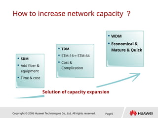
  • #5 SDM increases the transmission capacity linearly by adding the number of optical fibers, and the transmission equipment will be increased linearly, too. TDM keeps the same transmission medium but increases the bit rate. The equipment is getting more and more complicated and expensive. Additionally, the maximum transported capability over a fiber pair is in the range of a few 10Gbps. The way to scale to higher transported capacity is WDM. This technology keeps the same fiber, the same bit rate, but uses multiple colours to multiply transported capacity. WDM is widely used in the national and metro backbone transmission systems.
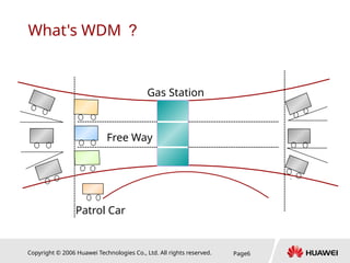
  • #6 Legend: Freeway: Fiber Patrol Car: Supervisory Signal Gas Station: Optical Relay Gray Car: Client Service Colored Car: Service in different channels (wavelength) Driveway: Optical Wavelength 
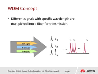
Wave Division Multiplexing is a technology that utilizes the properties of refracted light to both combine and separate optical signals based on their wavelengths within the optical spectrum.
  • #7 The Greek letter lambda (  ) , is often used to designate individual wavelengths. Key word in the content is specific wavelength. How specific ? Please refer to ITU-T series recommendations in chapter 4. WDM allows for a more efficient use of existing fiber by providing multiple optical paths along a single (pair of) fiber (s). WDM allows for a greater range of protocol transmission better suited than legacy network for data centric applications. (E.g.. GE, ESCON, Fiber Channel, D1 video)
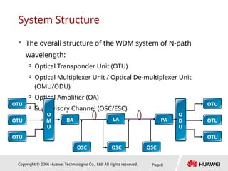
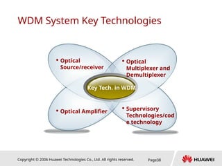
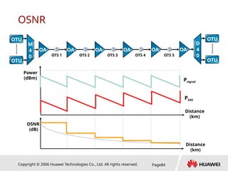
  • #8 OTU: Access the client service and convent the wavelength complied with ITU standards. OMU: Multiplex several services with different wavelength into one main path signal. ODU: Demultiplex one main path signal into several individual signals. OA: Amplifies the optical signal. OLA: Optical Line Amplifier OSC: Optical Supervisory Channel ESC: Electrical Supervisory Channel
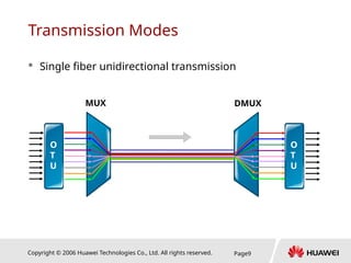
  • #9 Unidirectional WDM system adopts two optical fibers. One only implements the transmission of signals in one direction while the other implements the transmission of the signals in the opposite direction. Widely used in the worldwide.
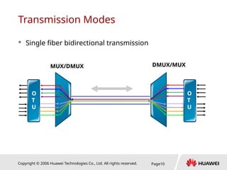
  • #10 Bi-directional wave WDM system utilizes only one optical fiber. The single fiber transmits optical signals in both directions simultaneously, and the signals in the different directions should be assigned on different wavelengths. Note: To MUX/DEMUX the signals in one fiber, circulator is recommended. This mode is usually used in the CWDM system to reduce the cost.
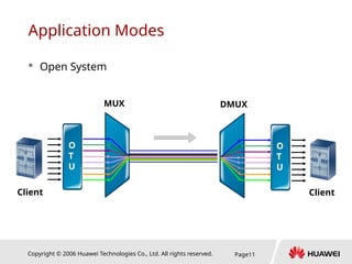
  • #11 Open system has no special requirements for multiplex terminal optical interfaces, the only requirement is that these interfaces meet the optical interface standards defined in ITU-T.
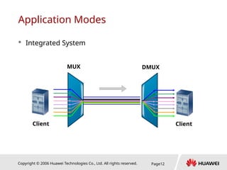
  • #12 Integrated system does not adopt the wavelength conversion technology, instead, it requires that the wavelength of the optical signals at the multiplex terminal conforms to the specifications for the WDM system. The optical interface in the client equipment that could provide standard wavelength is called colored interface. Huawei series OSN products could support this function.  Thought: Can some channels use OTU and some channels use colored interface?
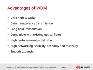
  • #13 Up to know the capacity is 1920Gbps at most. Data Transparency Transmission: WDM doesn’t change the structure or any byte in the frame for the client signal. Long Haul transmission: 5000km without REG / 230km long hop. Smooth expansion: modularization and no affect the existing services.
  • #16 Fill in the blanks: WDM System includes:________, _________, _________ and __________; CWDM system could use optical amplifiers (True or False) __________; ESC means____________________________________. Need additional wavelength to transmit in the fiber (True or False) _________. Single fiber bidirectional transmission (can or can not )_________ use the same wavelength for transmitting and receiving.
  • #18 Objectives for this chapter: List the characteristics of the fiber; Classify different types of the fiber; Outline the methods to against the factors.
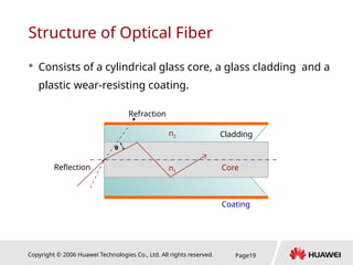
  • #19 An optical fiber consists of two different types of solid glass —the core and cladding—that are mixed with specific elements to adjust their refractive indices. The difference between the refractive indices of the two materials causes most of the transmitted light to bounce off the cladding and stay within the core. The critical angle requirement is met by controlling the angle at which the light is injected into the fiber. Two or more layers of protective coating around the cladding ensure that the glass can be handled without damage. N1 and N2, which one is larger ?
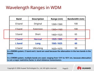
  • #22  Band Wavelength Bandwidth (nm) Original 1260~1360 100 Extended 1360~1460 100 Short 1460~1525 65 Conventional 1525~1565 40 Long 1565~1625 60 Ultra long 1625~1675 50 
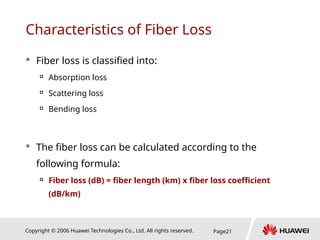
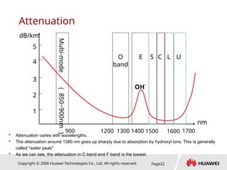
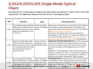
Combining the above losses, the attenuation constant of single mode fiber at 1310nm and 1550nm wavelength areas is 0.3~0.4dB/km (1310nm) and 0.17~0.25dB/km (1550nm), respectively. As defined in ITU-T Recommendation G.652, the attenuation constant at 1310nm and 1550nm should be less than 0.5dB/km and 0.4dB/km, respectively.
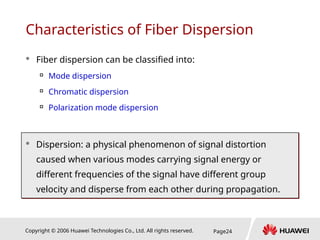
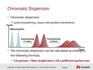
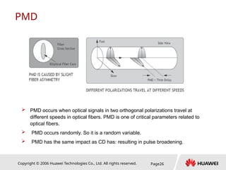
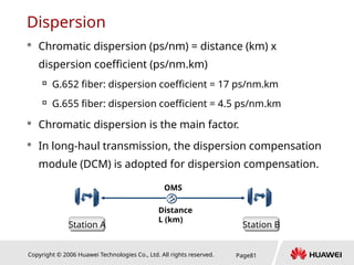
  • #25 Dispersion in fiber refers to a physical phenomenon of signal distortion caused when various modes carrying signal energy or different frequencies of the signal have different group velocity and disperse from each other during propagation.
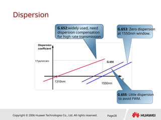
  • #28 G.652 fiber is currently a single mode fiber for widely use, called 1310nm property optimal single mode fiber and also called dispersion unshifted fiber. G.653 fiber is called dispersion shifted fiber or 1550nm property optimal fiber. By designing the refractive index cross section, the zero dispersion point of this kind of fiber is shifted to the 1550nm window to match the minimum attenuation window. This makes it possible to implement ultrahigh speed and ultra long distance optical transmission. G.655 fiber, a nonzero dispersion shifted single mode optical fiber, is similar to G.653 fiber and preserves certain dispersion near 1550nm to avoid four-wave mixing phenomenon in DWDM transmission. It is suitable for DWDM system applications.
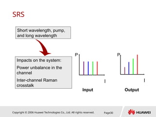
  • #30 Take the following measures to reduce SRS: Reduce the channel spacing. Keep the transmission power below the SRS threshold. Introduce certain dispersion.
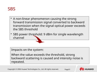
  • #31 Take the following measures to reduce SBS: Keep the single-channel power below the SBS threshold. Add the width of optical source to larger than 100 MHz (0.1 nm). Adopt phase modulation.
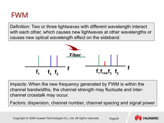
  • #33 The impact caused by FWM depends on the phase relation between interacted signals. If the interacted signals are transmitted at the same group speed (without dispersion), the impact is increased. On the other hand, if the system has dispersion, different signals are transmitted at different group speeds. Therefore, in-phase and inverse phase superposition between different waves may reduce the mixed frequency efficiency. In the systems with dispersion, the difference between group speeds varies directly with the channel spacing. The dispersion value in a dispersion shift fiber is low, but the FWM efficiency is high. In a dispersion shift fiber, when the channel number increases, more FWM options are introduced. When the channel spacing decreases, phase mismatch decreases and FWM efficiency increases. When the signal power increases, FWM increases exponentially.
  • #35  Fill in the blanks: The attenuation coefficient of G.652 fiber is __________; approximately ________ for engineering planning; The dispersion coefficient of G.655 at 1550nm window is_______________; The dispersion coefficient of G.652 at 1310nm window is__________; at 1550nm window is___________;
  • #36 Coating, Cladding, Core G.652, G.653, G.655 Attenuation, Dispersion, Nonlinear effect
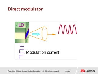
  • #40 Output laser is controlled by input current. The variation of the modulation current causes the variation of output wavelength. This variation, called modulation chirp, is actually a kind of wavelength (frequency) jitter inevitable for direct modulation of the sources. The chirp broadens the bandwidth of the emitting spectrum of the laser, deteriorates its spectrum characteristics and limits the transmission rate and distance of the system. 
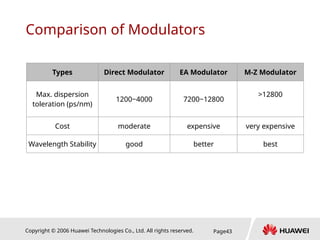
Transmission rate is limited to 2.5Gbit/s, and transmission distance is less than 100km. Similar Specification –This kind of modulator is Widely used in CWDM system.
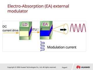
  • #41 EA modulator adopts different structure, use stable DC current to let LD output a standard wavelength (complied with ITU-T). EA module act as a door that open only happens to the current change. In this way, the information is modulated into the wavelength. Less chirp = Support long haul transmission (2.5Gb/s > 600km) High Dispersion tolerance (2.5Gb/s: 7200~12800ps/nm) Most widely used in DWDM
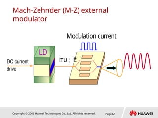
  • #42 This modulator separates the light input into two equal signals which enter the two optical branches of the modulator respectively. These two optical branches employ an electro-optical material whose refractive index changes with the magnitude of the external electrical signal applied to it. Changes of the refractive index of the optical branches will result in the change variation of the signal phases. Hence, when the signals from the two branches recombine at the output end, the combined optical signal is an interference signal with varying intensity. With this method, the frequency chirp of the separated external modulated laser can be equal to zero. Long dispersion limited distance High cost with good performance Negligible chirp Not widely used.
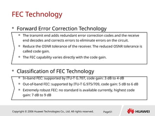
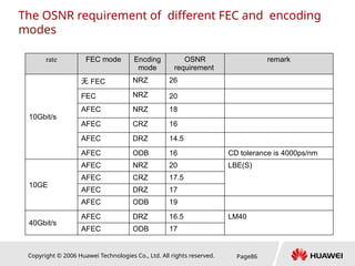
  • #51 Currently, forward error correction technology (FEC) can be classified into three types: In-band FEC Out-band FEC Extremely robust FEC (Super FEC, Advanced FEC, Extended FEC) In-band FEC is based on ITU-T G.707. The code gain is from 3 dB to 4 dB. As the gain in the ULH system is small, in-band FEC is not adopted. Out-band FEC is based on ITU-T G.975/709. The line rate is 10.66 Gbit/s or 10.709 Gbit/s, the code gain is from 5 dB to 6 dB, and the redundancy is 7%. G.975 adopts RS255 and RS239, and G.709 adopts RS255 and RS237. The extremely robust FEC adopts RS cascading code, Turbo code or Goppa code. In general, the code gain is from 7 dB to 9 dB. The redundancy is usually from 0% to 25%. Currently, no standard is available for the advanced FEC. Equipment vendors use private code technologies. The leading technology in the industry is to adopt the advanced FEC code, of which the code gain reaches 10 dB.
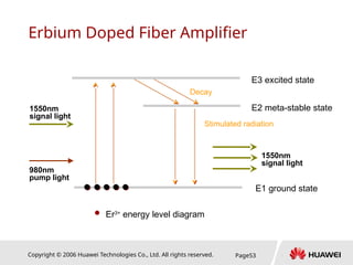
  • #53 Principle: The outer electrons of Er ions have 3 energy levels, where E1 is the basic state energy level, E2 is the metastable state energy level and E3 is the high energy level. When high-energy pump lasers are used to excite the EDF, lots of bound electrons of the erbium ions are excited from E1 to E3 level, then soon dropped to the E2 level via a non-radiation decay process (i.e. no photon but heat is released). When a signal with the wavelength of 1550nm passes through this erbium-doped fiber, particles in the metastable state are transited to the basic state via stimulated radiation and generate photons identical to those in the incident signal light.
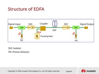
  • #54 TAP is used to spilt out a little part of energy and send it to the PD to detection. ISO is used to make sure the signal transmit in one direction. Pump laser has two type: with 980nm and with 1480nm. If we want to get a high gain, we could cascade EDF and pumping laser
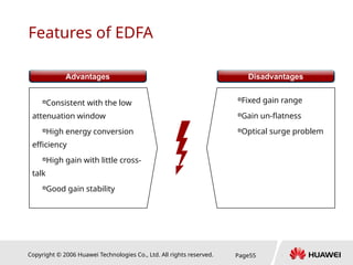
  • #55 Advantage: Fortunately, 1550nm is in the low attenuation window, the emergence of EDFA greatly activate the development of WDM. Disadvantage: Gain un-flatness
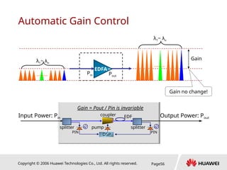
  • #56 If we cannot control the gain, optical surge generates. With AGC function: When add wavelengths from 1 to 40, the gain will be not changed. When drop wavelengths from 40 to 1, the gain will be not changed also Key Component is the DSP that makes the nonlinear calculation.
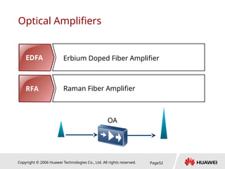
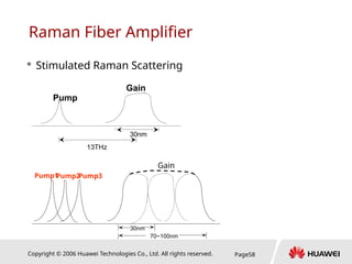
  • #58 Principle: Fiber has wide SRS gain spectrum and a wide gain peak around a frequency 13THz lower than that of the pumping light. If a weak signal and a strong pumping light wave are transmitted through the fiber at the same time, and the wavelength of the weak signal is set within the Raman gain bandwidth of the strong pumping light, the weak signal can be amplified. Such SRS-based OA is call Raman optical amplifier. Raman optical amplifier’s gain is the switch gain, that is, the difference between the output power when the amplifier is on and that when the amplifier is off.
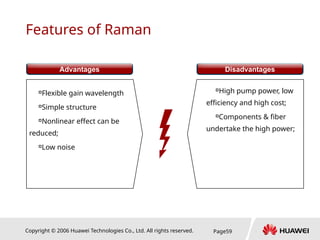
  • #59 Advantage: The gain wavelength is determined by the pumping light wavelength. The gain medium is the transmission fiber itself, low noise. As the amplification is distributed along the fiber with the comparatively low signal power, it reduces the interference from non-linear effect, especially FWM effect. Disadvantage: High power is harmful for body. Be careful when put operation on Raman.
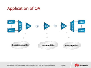
  • #60 According to its application: BA: Booster amplifier, mainly used in the transmit end. For the hardware description, you will see OBU card. LA: Line amplifier, mainly used in the amplifier station, could be recognized as BA+PA. For the hardware description, you will see OAU card. PA: Pre-amplifier, mainly used in the receive end. For the hardware description, you will see OPU card.
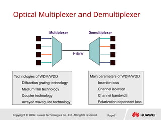
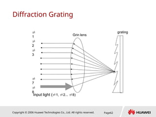
  • #62 (1) Principle It is an angular dispersion device. When the light is emitted to the grating, the angular dispersion function of the grating makes different optical signals radiate in different angles. These signals pass through the lens and are converged at different output fibers. As a result, wavelength selection and separation are successful. Wavelength combination can be implemented in the opposite way. (2) Advantages Good wavelength selection. The wavelength spacing can be shorten to about 0.5 nm. Parallel mechanism. The insertion loss does not increase with the increase of number of multiplexing channels. (3) Disadvantage Poor temperature stability
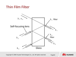
  • #63 Film Filter offers good stability and isolation between channels at moderate cost, but with a high insertion loss. So the number of dropping wavelength is limited.
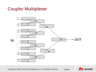
  • #64 (1) Principle Multiple fibers are fused so that multiple input wavelengths can be coupled. Thus, combination of wavelengths is achieved. However, it cannot divide different wavelengths. (2) Advantages Very good temperature feature Good optical channel bandwidth Simple and easy for mass production (3) Disadvantages Large size, poor channel isolation, and few wavelengths multiplexed
  • #65 The waveguides are connected to cavities at the input and output. When the light enters the input cavity, it is diffracted and enters the waveguide array. There the optical length difference of each waveguide introduces phase delays in the output cavity, where an array of fibers is coupled. The process results in different wavelengths having maximal interference at different locations, which correspond to the output ports.
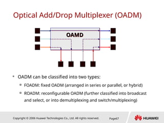
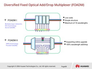
  • #69 Compared with the demultiplexing/switch/multiplexing scheme, the advantages of this scheme are listed as follows: ● Simple structure and better modularization for the upgrade ● lower cost when the number of add/drop wavelengths is small The disadvantages of this scheme are listed as follows: ● When the number of add/drop wavelengths is big, the cost is high. ● The transition to OXC in the future is difficult.
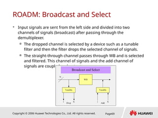
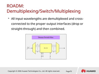
  • #70 The advantages of this scheme are listed as follows: ● When the number of add/drop wavelengths is big, the cost is low in contrast. ● It facilitates transition to OXC in the future. The disadvantages of this scheme are listed as follows: ● When the number of add/drop wavelengths is small, the cost is high. ● The modular extent is low and high cost forces original deployment. Otherwise high cost may become the bottleneck of future upgrade.
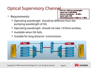
  • #72 Pumping wavelength of OA: 980nm or 1480nm. 1310nm already defined by ITU-T for future use. OA fails, all signal lost, requires the supervisory signal continue to transmit alarms and other indications. The receive sensitivity of the OSC unit is very good, up to -48dBm.
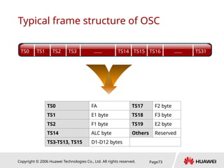
  • #73 FA: Frame alignment. E1 E2 : Orderwire. ALC: Automatic Level Control. F1 F2 F3 : transparent serials data. D1-D12: DCC bytes, data communication channel.
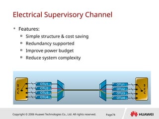
  • #74 The optical transponder unit (OTU) multiplexes the supervisory information into the service channel for transmission. The ESC reduces the investment of the OSC. It also deletes the insertion loss of the FIU. This lowers the cost and the power budget of optical channels.
  • #75  Fill in the blanks: EDFA means:______________________; its pumping wavelength is___________; We can calculate noise figure by _________。 AWG means:______________________; TFF means:________________________; OSC signal’s frame structure is_____________, (can, can not) by amplified by OA. ESC support OLA station ?_______(True, False)
  • #76 LD, EA, M-Z EDFA, Raman TFF, AWG OSC, ESC
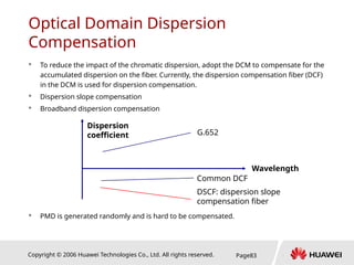
  • #82 Multi-slope DCF compensates for dispersion on a section basis. This is a common dispersion compensation technology. Adopts return to zero code (RZ), which is the basis of implementing dispersion compensation soliton (DMS). Electrical domain dispersion pre-compensation does not need any dispersion compensation module and has better adaptive abilities to the length of fiber-optic cables (about 50000 ps). When optical fibers are cut, the possibility of impacts on the system performance is sharply reduced. In addition, the WDM system and equipment structure can be simplified.
  • #83 DCF: Dispersion Compensation Fiber
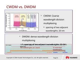
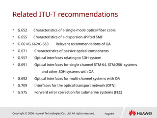
  • #89 ITU-G.692 – Optical Interfaces for Multi-Channel Systems with Optical Amplifiers This recommendation specifies multi-channel optical line system interfaces for the purpose of providing future transverse compatibility among such systems. The current recommendation defines interface parameters for systems of four, eight, and sixteen channels operating at bit rates of up to STM-16 on fibers, as described in Recommendations G.652, G.653, and G.655 with nominal span lengths of 80 km, 120 km, and 160 km and target distances between regenerators of up to 640 km. A frequency grid anchored at 193.1 THz with inter-channel spacing at integer multiples of 50 GHz and 100 GHz is specified as the basis for selecting channel central frequencies.