Downloaded 3,046 times

![Objectives [cont.]](https://image.slidesharecdn.com/3jk10358aaaawbzza1-13124702180646-phpapp01-110804100850-phpapp01/85/WDM-Basics-4-320.jpg)

![Table of Contents [cont.] Switch to notes view!](https://image.slidesharecdn.com/3jk10358aaaawbzza1-13124702180646-phpapp01-110804100850-phpapp01/85/WDM-Basics-6-320.jpg)
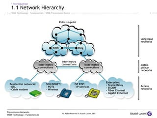
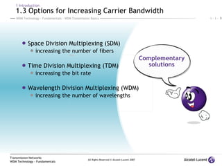
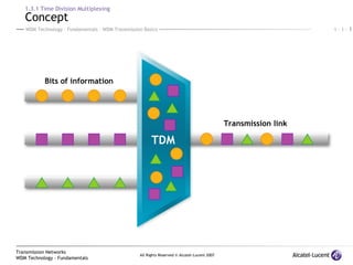
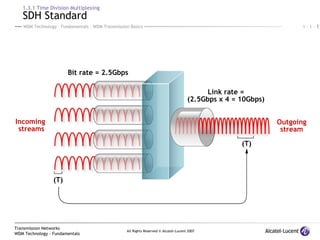
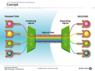
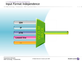
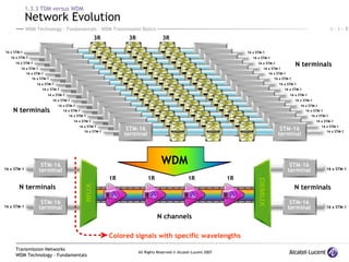
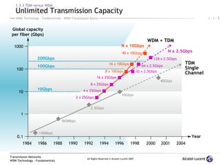
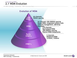
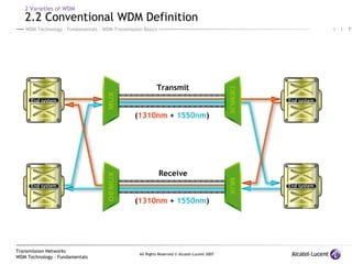
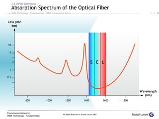
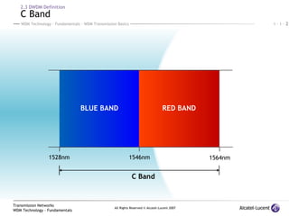
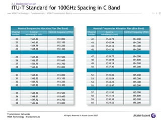
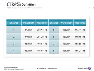

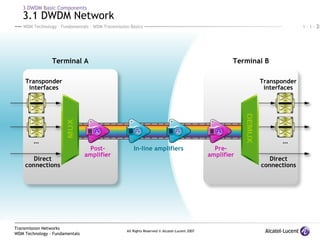
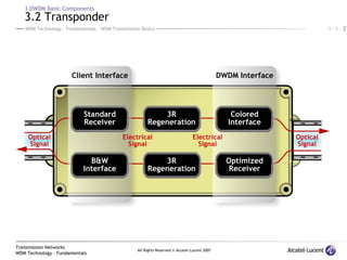
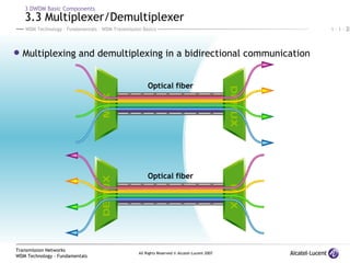
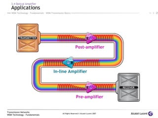
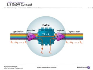


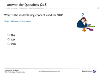
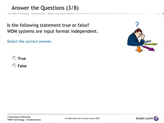
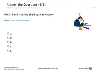
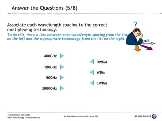
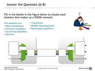
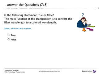


The document discusses wavelength division multiplexing (WDM) transmission basics. It describes: 1) Options for increasing bandwidth including SDM, TDM, and WDM. 2) Varieties of WDM including conventional WDM with 2 wavelengths, DWDM with 100GHz spacing in the C-band, and CWDM with 3000GHz spacing. 3) The components of a DWDM network including transmitters, multiplexers, amplifiers, optical fiber, and receivers.