Downloaded 1,732 times
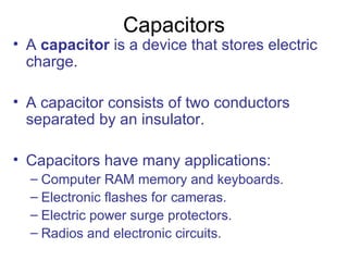

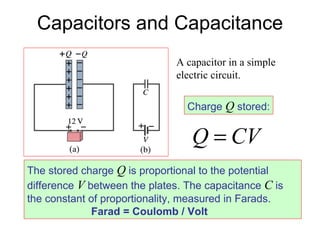


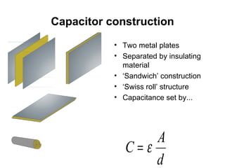
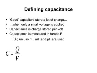


A capacitor is an electronic component that stores electric charge between two conductors separated by an insulator. Capacitors are used in applications like computer memory, camera flashes, and surge protectors. The amount of charge a capacitor can store is proportional to the potential difference between its plates and is known as its capacitance, measured in Farads. Common types of capacitors include parallel-plate and cylindrical capacitors.


