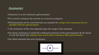
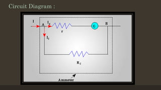
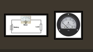
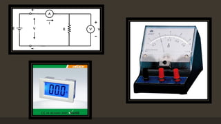
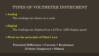
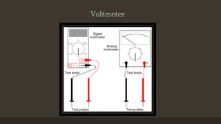
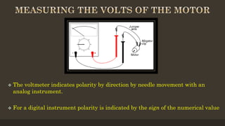
The document provides an overview of ammeters and voltmeters, explaining their functions in measuring electric current and voltage, respectively. Ammeter is described as a low-resistance device used in series to measure current, while a voltmeter measures potential difference across points in a circuit in parallel. Additionally, it covers the principles, types of measurements (analog and digital), and components essential for their operation.
Overview of the presentation topic focusing on Ammeter and Voltmeter in Basic Electronics.
Definition and function of an ammeter, current measurement, connection in series, low resistance characteristics, and circuit disturbance minimization.
Definition and application of voltmeter for measuring voltage across circuit elements, connection in parallel, and disturbance considerations.
Types of voltmeters (analog and digital), working principle related to Ohm's Law, and voltage indication of polarity in digital and analog formats.
Details about digital voltmeters, their measurements, components like integrators and ADC, importance of scaling, and display circuitry.
Closing remarks of the presentation, summarizing the discussed topics.
Ammeter and Voltmeter
SUB: Basic Electronics
Prepared by : PATEL RAVI V. (150410111065) Electronics And Communication Engg. (B.E) (SEM – 2)
2.
Ammeter
Ammeter is alow resistance galvanometer
It is used to measure the current in a circuit in amperes
Galvanometer can be converted into an ammeter by using a low resistance wire in
parallel with the galvanometer
the resistance of the wire depends upon the range of the ammeter
As shunt resistance is small the combined resistance of the galvanometer & the shunt
is very low hence the ammeter has much lower resistance than galvanometer
An ideal ammeter has zero resistance
Information :
Anammeter (the name is a contraction of ‘ampere-meter’) is a device for
measuring the electric current through a wire or a circuit element. An
ammeter is always connected in series with the element in question:
Note: the voltage drop across the ammeter itself disturbs the circuit into
which it is plugged in, and such disturbance may change the very current
the ammeter is used to measure. To minimize the disturbance, the
voltage across the ammeter should be as small as possible, which requires
that the electric resistance of the ommeter should be as small as possible.
7.
WHAT IS AVOLTMETER?
It is the most common instrument used to
measure voltage
It measure either AC or DC voltage
It is a measure of the voltage between two
points of an electrical current
8.
A voltmeteris a device for measuring potential difference (the voltage)
between two wires, usually across a circuit element or a group of
elements. A voltmeter is always connected in parallel with the
element(s) in question:
Note: the current flowing through the voltmeter itself disturbs the
circuit into which it is plugged in, and such disturbance may change the
very voltage the voltmeter is used to measure. To minimize the
disturbance, the current through the voltmeter should be as small as
possible, which requires that the electric resistance of the ommeter
should be as large as possible.
Information :
10.
Analog
The readingsare shown on a scale
Digital
The readings are displayed on a LCD or LED display panel
Work on the principle of Ohm’s Law
Potential Difference = Current × Resistance
(Volts)= (Amperes) × (Ohms)
The voltmeterindicates polarity by direction by needle movement with an
analog instrument.
For a digital instrument polarity is indicated by the sign of the numerical value
13.
When measuringa voltage difference there are always two leads coming from the
instrument that will have to be connected to the two points in your circuit across
which the voltage appears.
Voltage might be any of the following:
Across an element embedded in a circuit.
The output of a transducer measuring some physical variable like temperature, pH,
etc.
Digital Voltmeter is an instrument which use to measured the voltage & display the
measured voltage using LCDs or LEDs to display the result in a floating point
format. They are an instrument of choice for voltage measurements in all kinds of
situations.
Digital voltmeters usually have scales that are 0-0.3v, 0-3v, 0-30v, 0-300v.
14.
INTEGRATOR:-The integratorstabilizes the voltage as a first step in measuring it. It
takes a brief time sample, integrates it and outputs a proportional voltage. Integrating a
time sample makes the voltmeter more immune to noise in the signal.
ANALOG/DIGITAL CONVERTOR:-The analog/digital converter or ADC, is the heart of
the voltmeter. It is a clocked circuit that takes an input voltage sample and outputs a
number representing the voltage value. Since it's clocked, you get a steady stream of
numbers that change when the input voltage changes.
ZEROING&SAMPLING:-A digital voltmeter needs to know where zero is in order to give
a true reading. This is done with a precision zero reference voltage provided either
internal to the ADC chip or externally.
15.
For a general-purposevoltmeter, scaling is important. Scale can be switched automatically by
detecting overflow in the display.
DISPLAY:-Usually, four or more digits of accuracy, a minus sign, and a floating decimal
point are provided. Other indicators for battery status and range may also be included. A
well-designed integrator and ADC will keep the display from jittering between values;
otherwise usability suffers. For example, if the voltage is 5.21 volts, without some
stabilizing, the display might waver between 5.21 and 5.22.
The digit display needs driver circuitry to handle the drive current. The same ADC chip
frequently also has the display drivers also. Connecting the chip directly to the display
simplifies the design and adds reliability.