Downloaded 386 times
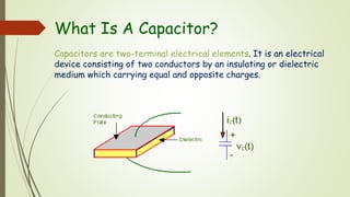


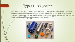
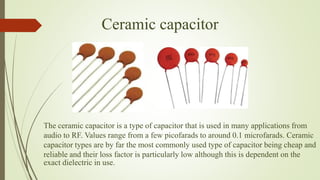
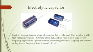
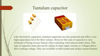
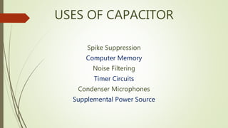
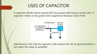


Capacitors are two-terminal electrical devices that store electric charge through two conductive plates separated by an insulating medium. They have various types and characteristics, including a nominal capacitance value indicated on their body, and they can be used in applications such as noise filtering and energy storage. Different capacitor types include ceramic, electrolytic, and tantalum, each with unique properties suited for specific uses.