Capacitors are devices used to store electric charge. They consist of two conductive plates separated by an insulator. The capacitance of a capacitor depends on the plate area, distance between plates, and the dielectric material between the plates. When a potential difference is applied across a capacitor's plates, electric charges of equal magnitude but opposite polarity build up on each plate.
#include <iostream>
using namespace std;
const int N = 40;
void sum(int*p, int n, int d[]){
int i;
*p = 0;
for(i = 0; i < n; ++i)
{
*p = *p + d[i];
}
}
int main(void){
int i;
int accum = 0;
int data[N];
for(i = 0; i < N; ++i)
{
data[i] = i;
}
sum(&accum, N, data);
cout<<"sum is " << accum << endl;
return 0;
}#include <iostream>
using namespace std
Electric Charge and Electric Field LectureFroyd Wess
More: http://www.pinoybix.org
Lesson Objectives:
Static Electricity; Electric Charge and Its Conservation
Electric Charge in the Atom
Insulators and Conductors
Induced Charge; the Electroscope
Coulomb’s Law
Solving Problems Involving Coulomb’s Law and Vectors
The Electric Field
Field Lines
Electric Fields and Conductors
Gauss’s Law
Electric Forces in Molecular Biology: DNA Structure and Replication
Photocopy Machines and Computer Printers Use Electrostatics
The following presentation is a part of the level 4 module -- Electrical and Electronic Principles. This resources is a part of the 2009/2010 Engineering (foundation degree, BEng and HN) courses from University of Wales Newport (course codes H101, H691, H620, HH37 and 001H). This resource is a part of the core modules for the full time 1st year undergraduate programme.
The BEng & Foundation Degrees and HNC/D in Engineering are designed to meet the needs of employers by placing the emphasis on the theoretical, practical and vocational aspects of engineering within the workplace and beyond. Engineering is becoming more high profile, and therefore more in demand as a skill set, in today’s high-tech world. This course has been designed to provide you with knowledge, skills and practical experience encountered in everyday engineering environments.
This is first PPT in the electrostatics series. This PPT presents idea of charge , its various methods of production like through conduction, friction, induction. It also describes working of electroscope & concept of grounding of an insulator.
Injection of the wind power into an electric grid affects the power quality. The performance of the wind turbine and thereby power quality are determined on the basis of measurements and the norms followed according to the guideline specified in International Electro-technical Commission standard, IEC-61400. The influence of the wind turbine in the grid system concerning the power quality measurements are-the active power, reactive power, variation of voltage, flicker, harmonics, and electrical behavior of switching operation and these are measured according to national/international guidelines. The paper study demonstrates the power quality problem due to installation of wind turbine with the grid. In this proposed scheme STATic COMpensator (STATCOM) is connected at a point of common coupling with a battery energy storage system (BESS) to mitigate the power quality issues. The battery energy storage is integrated to sustain the real power source under fluctuating wind power. The STATCOM control scheme for the grid connected wind energy generation system for power quality improvement is simulated using MATLAB/SIMULINK in power system block set. The effectiveness of the proposed scheme relives the main supply source from the reactive power demand of the load and the induction generator. The development of the grid co-ordination rule and the scheme for improvement in power quality norms as per IEC-standard on the grid has been presented.
This is a basic presentation about the Capacotors with iths basic knowledge about some equations also.
It is a little longer but you will get the general information about the capacitors.
It is well divided into 4 portions.
Capacitors Presentation
Presentations about capacitors
What is capacitor
Construction of capacitor
by Mudasir Nadeem
Institute of Chemical Sciences BZU Multan
A cylindrical capacitor is a specific type of capacitor characterized by its cylindrical structure. It consists of two coaxial (aligned along the same axis) cylinders or conductors, one inside the other, separated by a dielectric material.
Here are the key components and characteristics of a cylindrical capacitor:
1. **Structure**: It comprises an inner cylinder and an outer cylinder, both arranged along the same axis. The space between these cylinders is filled with a dielectric material that prevents direct electrical contact between the cylinders.
2. **Dielectric Medium**: The dielectric material, which could be air, vacuum, or other non-conductive substances, helps in maintaining a potential difference between the cylinders without allowing the flow of current between them.
3. **Capacitance Factors**: The capacitance of a cylindrical capacitor is influenced by several factors, including the radii of the cylinders, their lengths, and the properties of the dielectric material between them. Formulas exist to calculate the capacitance based on these parameters.
4. **Applications**: Cylindrical capacitors find applications in various fields such as electronics, power systems, and telecommunications due to their relatively high capacitance compared to other capacitor designs. They are utilized where efficient energy storage in a compact form is required.
5. **Energy Storage**: During charging, energy from an external source is expended to charge the capacitor. This energy gets stored within the electrostatic field formed in the dielectric material. Upon discharge, this stored energy is released.
6. **Functions**: Cylindrical capacitors serve multiple functions, including energy storage, signal processing in circuits, filtering, and regulation of electrical energy in power transmission systems.
In summary, cylindrical capacitors are a specific design of capacitors consisting of coaxial cylinders separated by a dielectric medium. Their structure and properties make them valuable in various technological applications where efficient energy storage and manipulation of electrical signals are required.
2. Capacitors
• A capacitor is a device for storing electric charge.
• It can be any device which can store charges.
• Basically, capacitors consists of two metal plates
separated by an insulator. The insulator is called
dielectric. (e.g. polystyrene, oil or air)
• Circuit symbol:
+
_
Dielectric
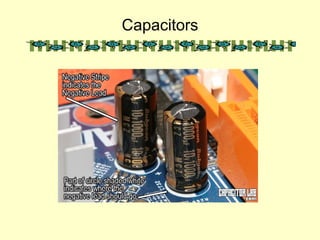
3. Examples of Capacitors
• Paper, plastic, ceramic
and mica capacitors
• Electrolytic capacitors
• Air capacitors
7. Charging a Capacitor (2)
• Voltage-charge
characteristics
• Current flow
I
t
Vc
or
Q
t
)1(0
RC
t
C eVV
−
−=
RC
t
oeII
−
=
Vc ∝ Q
8. Charging of capacitors
• When a capacitor is connected across a battery, electrons
flow from the negative terminal of the battery to a plate of
the capacitor connected to it. At the same rate, electrons
flow from the other plate of the capacitor to the positive
terminal of the battery. This gives a flow of current as the
capacitor is being charged.
• As charges accumulate on the plates of the capacitor,
electric potential built across the plates. This hinders
further accumulation of charges and makes the charge
up current decreasing. When the potential difference
across the plates equals that of the battery, the current
becomes zero.
11. Discharging a Capacitor (2)
• Voltage-charge
characteristics
• Current flow
VC
or
Q
t
I
t
RC
t
eQQ
−
= 0
RC
t
oeII
−
=
12. Capacitance (1)
• Consider any isolated pair of conductors with
charge Q
Capacitance is defined as
V
Q
C =
where Q = charge on one conductor
V = potential difference between two conductors
Unit : farad (F)
13. Capacitance of a Capacitor
• Note that Q is not the net charge on the capacitor, which is
zero.
• Capacitance is a measure of a capacitor's ability to store
charge.
• The more charge a capacitor can hold at a given potential
difference, the larger is the capacitance.
• Capacitance is also a measure of the energy storage capability
of a capacitor.
• Unit of capacitance: CV-1
or farad (F).
• Farad is a very large unit. Common units are 1µF = 10-6
F, 1nF =
V
Q
C =
14. Markings of capacitor
• Consider a ‘6.3V 1500µF’
capacitor shown in the following
figure. Note that:
• (1) Maximum voltage across the
capacitor should not exceed 6.3 V,
otherwise (leakage or) breakdown
may occur.
• (2) Capacitance of 1500µF means
the capacitor holds 1500µC of
charge for every 1 V of voltage
across it.
15. Example 1
• Find the maximum charge stored by the capacitor shown in
the figure above.
• Solution:
16. Capacitance of an isolated conducting
sphere
• Capacitance = Q/V
• For an isolated conducting
sphere,
+
+
+
+
+
+
+
+ a
Q
V ⋅=
πε4
1
• ∴ C = Q/V = 4πεa
Q
- - - - - - - -
17. Example 2
• Find the capacitance of the earth given that the radius of
the earth is 6 x 10⁶
m.
• Solution
18. • Note:
• The earth’s capacitance is large compared
with that of other conductors used in
electrostatics. Consequently, when a
charged conductor is ‘earthed’, it loses most
of its charge to the earth or discharged.
19. Parallel Plate Capacitor
• Suppose two parallel plates of a capacitor
each have a charge numerically equal to Q.
• As C = Q/V
where Q = εEA and V = Ed
∴ C = εA/d
• C depends on the geometry of the conductors.
+Q
–Q
d
area A
Electric field
strength
εε
σ
A
Q
E ==
20. • Geometrical properties of capacitor
• Parallel plate capacitor capacitance depends
on area and plate separation. For large C,
we need area A large and separation d
small.
d
A
C
ε
=
21. Example 3
• The plates of parallel-plate capacitor in vacuum are 5 mm
apart and 2 m2
in area. A potential difference of 10 kV is
applied across the capacitor. Find
(a) the capacitance
• Solution
22. Example 3
• The plates of parallel-plate capacitor in vacuum are 5 mm
apart and 2 m2
in area. A potential difference of 10 kV is
applied across the capacitor. Find
(b) the charge on each plate, and
• Solution
23. Example 3
• The plates of parallel-plate capacitor in vacuum are 5 mm
apart and 2 m2
in area. A potential difference of 10 kV is
applied across the capacitor. Find
(c) the magnitude of the electric field between the plates.
• Solution
24. Application – variable
capacitors
• A variable capacitor is a capacitor
whose capacitance may be
intentionally and repeatedly changed
mechanically or electronically
• Variable capacitors are often used in
circuits to tune a radio (therefore they
are sometimes called tuning
capacitors)
• In mechanically controlled variable
capacitors, the amount of plate
surface area which overlaps can be
changed as shown in the figure below.
simulation
25. Permittivity of dielectric between
the plates
• A dielectric is an insulator
under the influence of an
E field. The following
table shows some
dielectrics and their
corresponding relative
permittivity.
• Capacitance can be
increased by replacing the
dielectric with one of
higher permittivity.
Dielectric Relative
permittivity
Vacuum 1
Air 1.0006
Polythene 2.3
Waxed paper 2.7
Mica 5.4
Glycerin 43
Pure water 80
Strontium
titanate
310
d
A
C
ε
=
26. Action of Dielectric (1)
• A molecule can be regarded as a collection of atomic
nuclei, positively charged, and surrounded by a cloud of
negative electrons.
+
- -
- -
- -
no field
no net charge Field
+
- -
- -
- -
net -ve
charge
net +ve
charge
• When the molecule is in an electric field, the nuclei are
urged in the direction of the field, and the electrons in
the opposite direction.
• The molecule is said to be polarized.
27. Action of Dielectric (2)
• When a dielectric is in a charged capacitor, charges
appear as shown below.
• These charges are of opposite sign to the charges on
the plates.
• The charges reduce the electric
field strength E between the plates.
• The potential difference between
the plates is also reduced as E = V/d.
• From C = Q/V, it follows that C is
increased.
28. Capacitors in series and parallel
• Computer simulation 1
• Computer simulation 2
29. Formation of a Capacitor
• Capacitors are formed all
of the time in everyday
situations:
– when a charged
thunderstorm cloud
induces an opposite
charge in the ground
below,
– when you put your hand
near the monitor screen of
this computer.
30. Charged Capacitor
• A capacitor is said to be charged when
there are more electrons on one
conductor plate than on the other.
When a capacitor is
charged, energy is
stored in the
dielectric material in
the form of an
electrostatic field.
31. Functions of Dielectrics
• It solves the mechanical problem of
maintaining two large metal plates at a very
small separation without actual contact.
• Using a dielectric increases the maximum
possible potential difference between the
capacitor plates.
• With the dielectric present, the p.d. for a given
charge Q is reduced by a factor εr and hence
the capacitance of the capacitor is increased.
32. Relative permittivity and Dielectric Strength
• The ratio of the capacitance with and without
the dielectric between the plates is called the
relative permittivity. or dielectric constant.
ov
d
r
C
C
ε
ε
ε ==
• The strength of a dielectric
is the potential gradient
(electric field strength) at
which its insulation breakdown.
33. Relative permittivity of some dielectrics
Dielectric Relative permittivity
Vacuum 1
Air 1.0006
Polythene 2.3
Waxed paper 2.7
Mica 5.4
Glycerin 43
Pure water 80
Strontium titanate 310
34. Capacitance of Metal Plates
• Consider a metal plate A which
has a charge +Q as shown.
• If the plate is isolated, A will
then have some potential V
relative to earth and its
capacitance C = Q/V. A
+Q
+V
• Now suppose that another metal B is brought
near to A.
B
-q +q
•So C’ = Q/V’ > C.
•Induced charges –q and +q are then obtained
on B. This lowers the potential V to a value V’.
35. Combination of Capacitor (1)
• In series
321 QQQQ ===
321 VVVV ++=
321
1111
CCCC
++=
321
321
1
:
1
:
1
::
CCC
VVV =
The resultant capacitance is smaller than the smallest
Individual one.
36. Combination of Capacitors (2)
• In parallel
321 QQQQ ++=
321 VVVV ===
321 CCCC ++=
321321 :::: CCCQQQ =
The resultant capacitance is greater
Than the greatest individual one.
37. Measurement of Capacitance using
Reed Switch
• The capacitor is charged at a frequency f to
the p.d V across the supply, and each time
discharged through the microammeter.
µAV+
-
V
During each time
interval 1/f, a charge
Q = CV is passed
through the
ammeter.
fCV
Q
I
f
==∴
1
38. Stray Capacitance
• The increased capacitance due to nearby
objects is called the stray capacitance Cs which
is defined by
• C = Co + Cs
– Where C is the measured capacitance.
• Stray capacitance exists in all circuits to some
extent. While usually to ground, it can occur
between any two points with different potentials.
• Sometimes stray capacitance can be used to
advantage, usually you take it into account but
often it's a monumental pain.
39. Measurement of Stray Capacitance
• In measuring capacitance of a
capacitor, the stray capacitance can be
found as follows:
C
s 1/d
C
0
s
o
C
d
A
C +=
ε
40. Time Constant (τ)
∀ τ = CR
• The time constant is used to measure how long
it takes to charge a capacitor through a resistor.
• The time constant may also be defined as the
time taken for the charge to decay to 1/e times
its initial value.
• The greater the value of CR, the more slowly
the charge is stored.
• Half-life
– The half-life is the time taken for the charge in a
capacitor to decay to half of its initial value.
– T1/2 = CR ln 2
41. Energy Stored in a Charged Capacitor
• The area under
the graph gives
the energy stored
in the capacitor.
0
Q
V
QVE
2
1
=
2
2
1
CV=
C
Q2
2
1
=
42. Applications of Capacitors (1)
• Press the key on a computer
keyboard reduce the capacitor
spacing thus increasing the
capacitance which can be
detected electronically.
• The capacitance is varied by
altering the overlap between
a fixed set of metal plates
and a moving set. These are
used to tune radio receiver.
43. Applications of Capacitors (2)
• Condenser microphone
– sound pressure changes the
spacing between a thin
metallic membrane and the
stationary back plate. The
plates are charged to a total
charge
– A change in plate spacing will
cause a change in charge Q
and force a current through
resistance R. This current
"images" the sound pressure,
making this a "pressure"
microphone.
44. Applications of Capacitors (3)
• Electronic flash on a camera
– The battery charges up the
flash’s capacitor over several
seconds, and then the capacitor
dumps the full charge into the
flash tube almost instantly.
– A high voltage pulse is generated
across the flash tube.
– The capacitor discharges
through gas in the the flash tube
and bright light is emitted.